Illumination apparatus

a technology of illumination apparatus and illumination lamp, which is applied in the direction of electrical apparatus, instruments, basic electric elements, etc., can solve the problems of undesirable moiré and mura (non-uniformity) artefacts, non-uniform spatial distribution of output luminance of catadioptric optical elements, etc., and achieves the reduction of cost and complexity of manufacture, convenient formation, and increased uniform output.

Active Publication Date: 2020-04-23
OPTOVATE
View PDF0 Cites 14 Cited by
  • Summary
  • Abstract
  • Description
  • Claims
  • Application Information

AI Technical Summary

Benefits of technology

[0017]It would be desirable to provide increased spatial uniformity for a directional display backlight comprising catadioptric optical elements in a thin package with high efficiency and high resolution.
[0054]According to a fifth aspect of the present disclosure there is provided an illumination apparatus, comprising: a plurality of micro-LEDs, the plurality of micro-LEDs being arranged in a micro-LED array; a plurality of catadioptric optical elements arranged in a catadioptric optical element array, wherein each of the catadioptric optical elements of the plurality of catadioptric optical elements comprises, in at least one cross-sectional plane through its optical axis: a first outer surface and a second outer surface facing the first outer surface; wherein the first and second outer surfaces extend from a first end of the catadioptric optical element to a second end of the catadioptric optical element, the second end of the catadioptric optical element facing the first end of the catadioptric element; wherein the distance between the first and second outer surfaces at the first end of the catadioptric optical element is less than the distance between the first and second outer surfaces at the second end of the catadioptric optical element; and at least one transparent inner surface arranged between the first and second ends and between the first and second outer surfaces; wherein each of the catadioptric optical elements of the plurality of catadioptric optical elements is aligned in correspondence with a respective one or more of the micro-LEDs of the plurality of micro-LEDs, each of the micro-LEDs of the plurality of micro-LEDs being aligned with only a respective one of the catadioptric optical elements of the plurality of catadioptric optical elements; the alignment being such that some of the light output from each of the micro-LEDs exits the second end of its respective catadioptric optical element with a first light output distribution; one or more reflective members, the one or more reflective members arranged relative to the first light output distribution such that some of the light that exits the second end of the respective catadioptric optical element is reflected by the one or more reflective members back into the catadioptric optical element; and a plurality of light recycle systems, the plurality of light recycle systems being arranged in an array, wherein each of the light recycle systems of the plurality of light recycle systems is aligned in correspondence with a respective micro-LED of the plurality of micro-LEDs, each of the light recycle systems being arranged relative to the first end of the catadioptric optical element and the one or more reflective members such as to further reflect some of said light that has been reflected back into its respective catadioptric optical element to provide recycled light that exits the second end of its respective catadioptric optical element with a second light output distribution, thereby providing a combined light output distribution comprising in combination the first light output distribution and the second light output distribution, the combined light output distribution having increased spatial uniformity compared to the spatial uniformity of the first light output distribution alone.

Problems solved by technology

Such catadioptric optical elements provide non-uniform spatial distributions of output luminance for some viewing angles.
In backlight arrangements, such non-uniform spatial distributions may provide Moiré and mura (non uniformity) artefacts that are undesirable.

Method used


Image

  • Illumination apparatus
  • Illumination apparatus
  • Illumination apparatus

Examples


Embodiment Construction

[0168]It would be desirable to provide a directional backlight for transmissive spatial light modulators such as liquid crystal displays with high spatial uniformity for directional viewing.

[0169]The operation of directional displays comprising plurality of micro-LEDs 3 and corresponding plurality of catadioptric optical elements 38 will first be described.

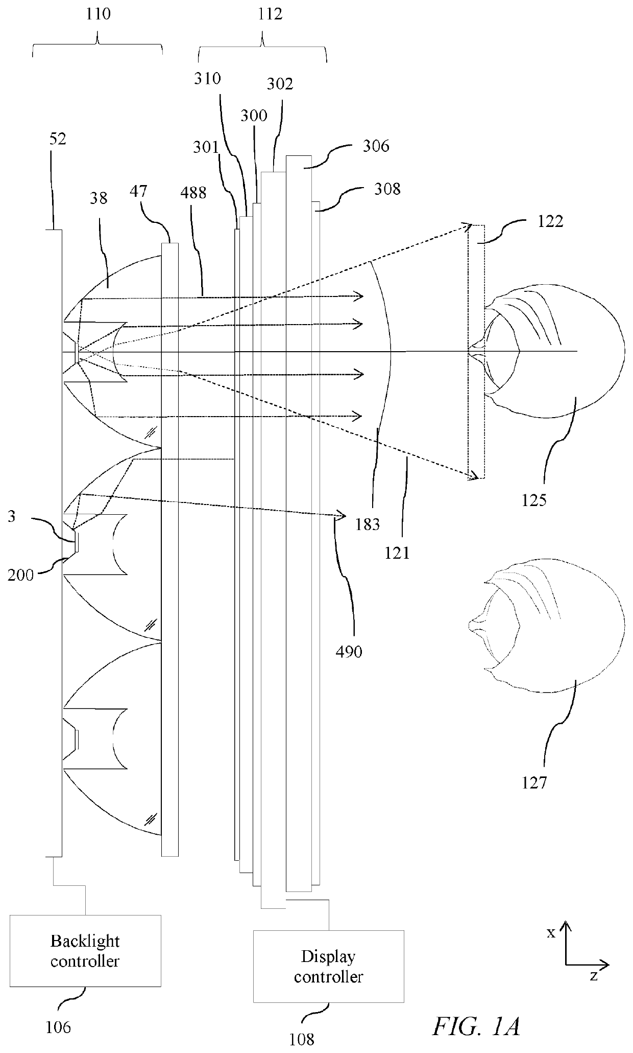
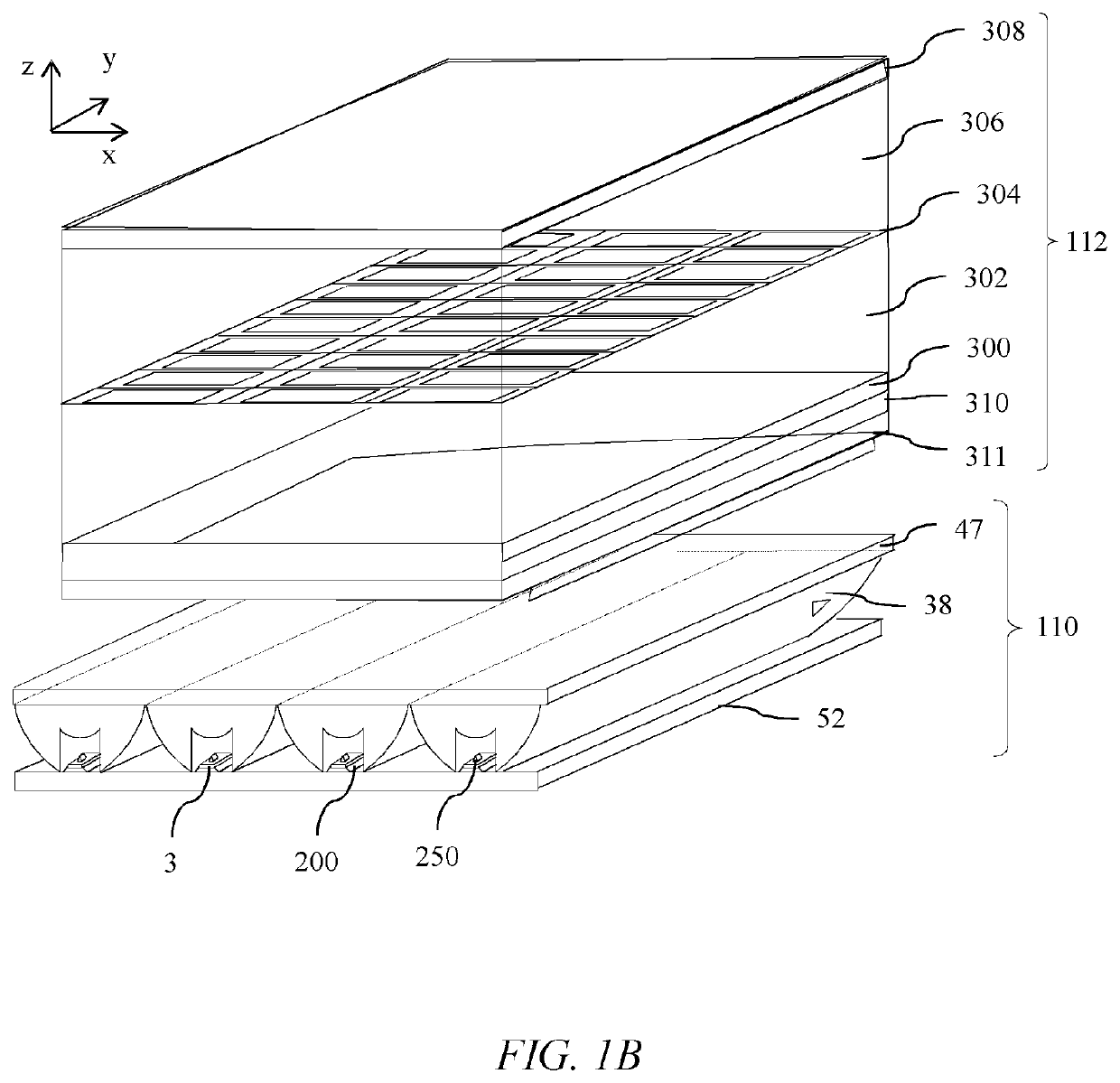
[0170]FIG. 1A is a schematic diagram illustrating a top view of a directional display comprising a spatial light modulator 112 and a directional backlight 110 comprising a plurality of micro-LEDs 3 that are each aligned with regions 204 of light deflecting surfaces 200; and a plurality of one dimensional catadioptric optical elements 38 that are linearly extended. FIG. 1B is a schematic diagram illustrating a perspective side view of the directional display of FIG. 1A. The catadioptric optical elements 38 are extended in the y direction, that may be the vertical direction for a display user.

[0171]Thus an illumination apparatus may...


PUM

PropertyMeasurementUnit
diameteraaaaaaaaaa
diameteraaaaaaaaaa
diameteraaaaaaaaaa

Abstract

An illumination apparatus comprises an array of micro-LEDs, an aligned plurality of directional catadioptric optical elements, light redirecting micro-optics and a reflective polariser. The directional illumination apparatus is arranged to provide a uniform spatial distribution across its output area by recirculating reflected high luminous intensity regions into low luminous intensity regions of the catadioptric optical element. A thin and efficient illumination apparatus with high spatial uniformity may be provided for illumination in environmental lighting, display backlighting or direct display.

Description

TECHNICAL FIELD[0001]The present disclosure relates to an apparatus comprising a plurality of addressable light-emitting elements aligned to a plurality of optical elements. Such an apparatus may be used for environmental lighting, for indoor or outdoor electronic display screens, or for a backlight to an LCD display.BACKGROUND[0002]Displays with wide directional light output distributions are typically used to achieve comfortable display viewing from many different viewing angles. Such displays are desirable for multiple users to share image content, and for displays where the viewing position is not substantially fixed in relation to the display centreline.[0003]By way of comparison displays with narrow directional light output distributions are typically used to provide image data for the eyes of users over reduced viewing angles. Such displays are typically used to achieve privacy display (where images that may be seen by snoopers are suppressed), night time display (where ambie...

Claims


Application Information

Patent Timeline
Patent Type & Authority Applications(United States)
IPC IPC(8): G02B19/00G02F1/1335G09G3/34H01L33/60H01L25/075
CPCG09G3/3406G02F2001/133607H01L33/60G02B19/0066G02F1/133605H01L25/0753G02F1/133603G02F1/133611G02B19/0028G02F1/133606H01L33/58G02B19/0061G02F1/133607
Inventor WOODGATE, GRAHAM J.HARROLD, JONATHAN
Owner OPTOVATE
Why Eureka
Try Eureka