Ceiling light fixture

Inactive Publication Date: 2020-04-30
TURNER MICHAEL
View PDF10 Cites 0 Cited by
  • Summary
  • Abstract
  • Description
  • Claims
  • Application Information

AI Technical Summary

Benefits of technology

The present invention provides a recessed light fixture for installation in a ceiling of an office or commercial building that allows for the control of the intensity of the emanating light. It is also suitable for retrofit situations involving the replacement of fluorescent tube fixtures. Additionally, the recessed light fixture prevents glare.

Problems solved by technology

First, they do not allow for any air-flow to pass therethrough.
In some instances, this lack of air-flow can lead to undesirable heat build-up.
In both situations, a significant problem with LED light tubes and strips is that the light produced thereby is generally harsher and of higher intensity than that produced by non-LED light sources, even where the nominal power rating is the same as between the original and the replacement light sources.
Moreover, LED light sources are inherently prone to more glare and eye strain than fluorescent light sources, most likely attributable to the higher wavelengths and pulsing nature of the light they emit.
Such linearly arranged sources produce uneven light distribution with hot spots along their lengths.
The simple regular pattern of small perforations in diffusers such as those taught in the Holder patent cannot compensate for such glare and hot spots and uneven light distribution along the length of LED light tubes.

Method used


Image

  • Ceiling light fixture
  • Ceiling light fixture
  • Ceiling light fixture

Examples


first embodiment

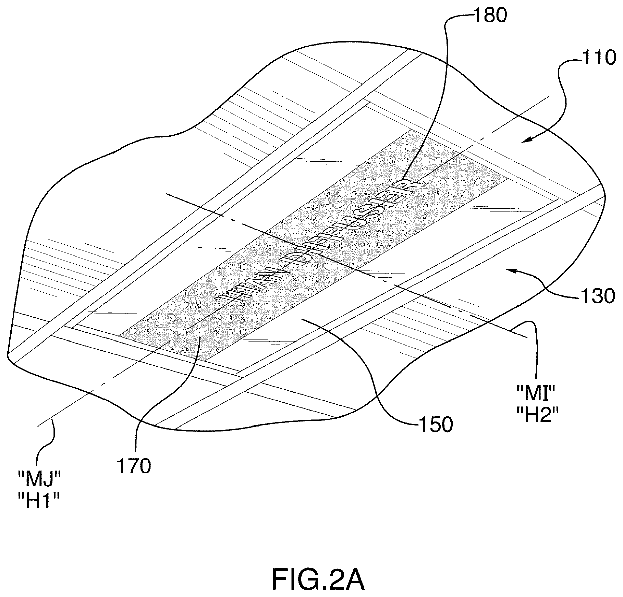
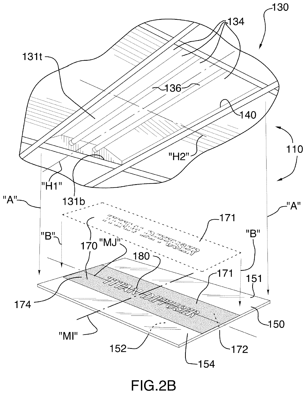
[0046]In FIG. 2A, the first exemplary embodiment of the discontinuous light diffuser 170 is shown in solid outline in place on the continuous light diffuser 150. In FIG. 2B, the first exemplary embodiment of the discontinuous light diffuser 170 is shown in dashed outline vertically separated from the continuous light diffuser 150, as indicated by arrows “A”, before being placed thereon, and is shown in solid outline once the discontinuous light diffuser 170 has been placed on the continuous light diffuser 150, as indicated by arrows “B”. As can be readily seen, the discontinuous light diffuser 170 is positioned with its second surface 172, which faces downwardly in the figures, in contacting relation with the first surface 151, which faces upwardly in the figures, of the continuous light diffuser 150. In this manner, the first exemplary embodiment of the discontinuous light diffuser 170 according to the present invention sits in an operative position atop, and supported by, the cont...

third exemplary embodiment

[0072]Reference will now be made to FIGS. 6A through 6F to discuss the fourth exemplary embodiment of the present invention. In brief, the fourth exemplary embodiment according to the present invention is similar to the third exemplary embodiment in that it comprises, in combination as indicated by general reference numeral 410, a ceiling light fixture housing as indicated by the general reference numeral 430, a continuous light diffuser 450, and a discontinuous light diffuser 470. The ceiling light fixture housing 430, the continuous light diffuser 450, and the discontinuous light diffuser 470 are the same as the ceiling light fixture housing 430, the continuous light diffuser 450 and the discontinuous light diffuser 470, respectively, in the third exemplary embodiment combination 410. Additionally, the fourth exemplary embodiment of the combination 410 further comprises supplemental means 490 for attaching the discontinuous light diffuser 470 in contacting relation with the contin...

exemplary embodiment 310

[0073]As can be best seen in FIGS. 6C and 6D, the installation of the continuous light diffuser 450 and the discontinuous light diffuser 470 is the same as described with respect to the continuous light diffuser 350 and the discontinuous light diffuser 370 in the third exemplary embodiment 310 of the present invention. With the continuous light diffuser 450 in the position shown in dashed outline in FIG. 6D, the first side edge 456a of the continuous light diffuser 450 is engaged on the first angled flange 441a of the ceiling light fixture housing 430, and the continuous light diffuser 450 is bent and moved upwardly, as indicated by arrow “G”, to allow the second side edge 456b to engage on the second angled flange 441b.

[0074]Similarly, the discontinuous light diffuser 470 is moved upwardly to be in partial contact with the continuous light diffuser 450, as indicated by arrow “H” in FIG. 6C to a position as also shown in FIG. 6C and as shown in dashed outline in FIG. 6D, whereat th...


PUM


Abstract

A light fixture housing contains an LED light source. A continuous light diffuser having a main body portion is defined between a first surface and a second surface of the continuous light diffuser, and is positioned within the housing to fully cover a light emitting opening formed in the housing. A discontinuous light diffuser having a main body portion is defined between a first surface and a second surface of the discontinuous light diffuser. A plurality of openings pass from the first surface of the discontinuous light diffuser through the main body portion to the second surface of the discontinuous light diffuser. The discontinuous light diffuser is positioned with its body portion in adjacent relation to either one of the first surface and the second surface of the continuous light diffuser so as to occlude a portion of the light emitting opening.

Description

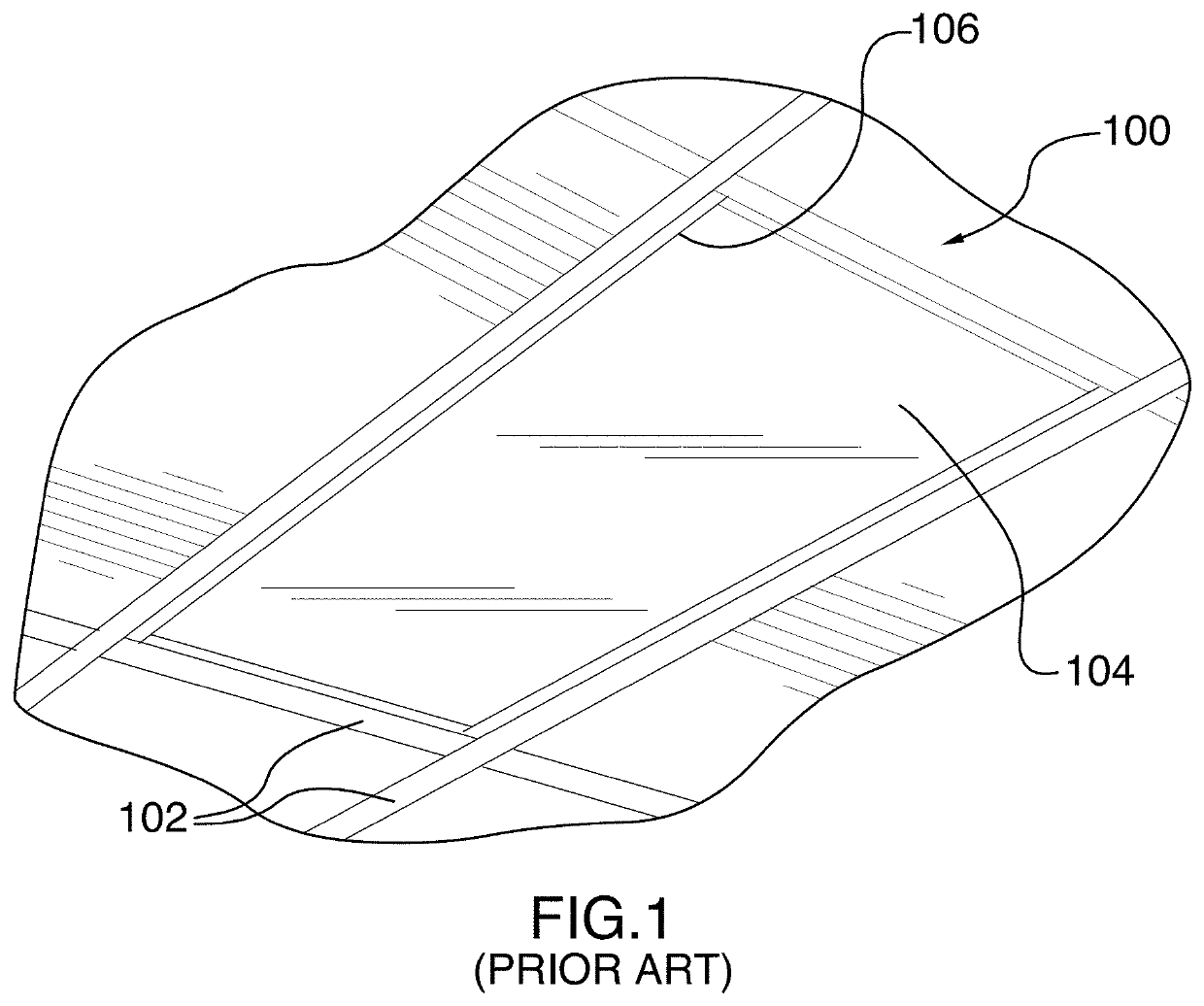
FIELD OF THE INVENTION[0001]The present invention relates to recessed light fixtures for installation in ceilings in commercial buildings, and more particularly to such recessed light fixtures having central diffusers.BACKGROUND AND SUMMARY OF THE INVENTION[0002]The use of fluorescent lighting systems has been known in commercial buildings for many years. In office and commercial environments and the like, fluorescent lighting systems typically are ceiling mounted and comprise a recessed light fixture having a metal housing having a bottom opening. One or two elongate fluorescent light tubes are typically mounted in the housing to shine generally downwardly. One or more large reflecting surfaces may be used to reflect light from the fluorescent light tubes. The large reflecting surfaces may be part of the housing or may be separate elements mounted in the housing. A light diffuser is typically disposed at the bottom opening to diffuse light emanating from the fluorescent light tubes...

Claims


Application Information

Patent Timeline
IPC IPC(8): F21V3/04F21V3/02F21S8/02G09F13/04G09F23/00
CPCF21S8/026F21V3/02F21V3/049G09F13/0413G09F23/00F21Y2115/10G09F2013/0436G09F2013/0481F21W2121/00G09F13/0436G09F13/0481
Inventor TURNER, MICHAEL
Owner TURNER MICHAEL
Why Eureka
Try Eureka