Lumbar support seat
- Summary
- Abstract
- Description
- Claims
- Application Information
AI Technical Summary
Benefits of technology
Problems solved by technology
Method used
Image
Examples
embodiment 1
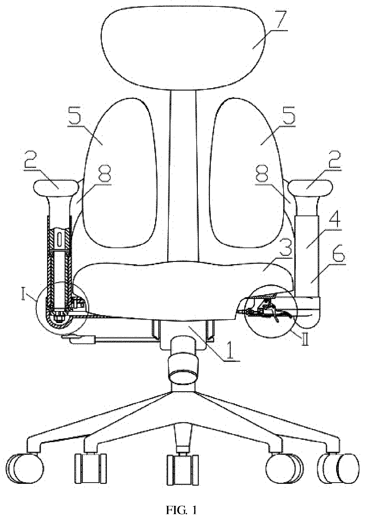
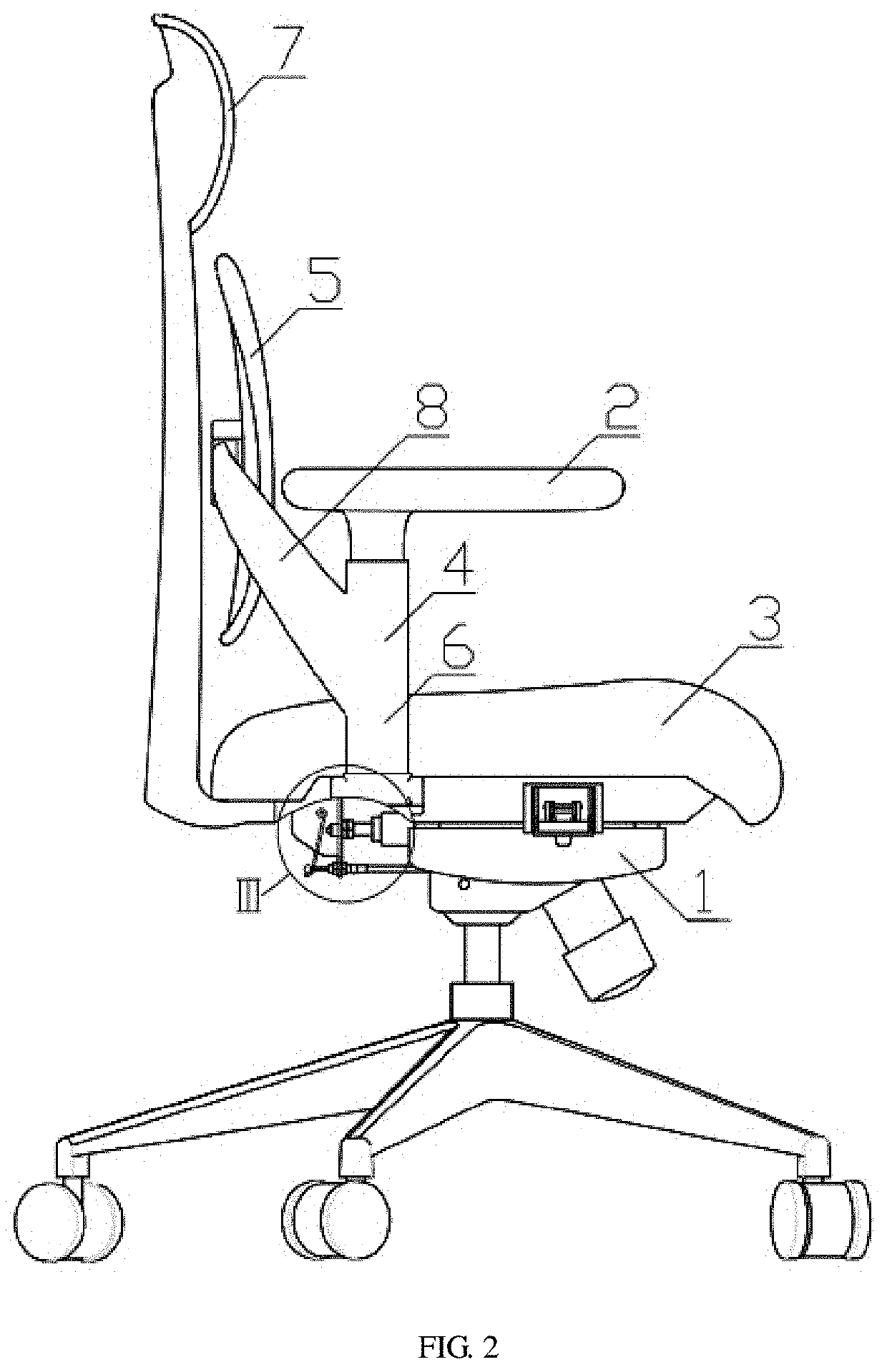
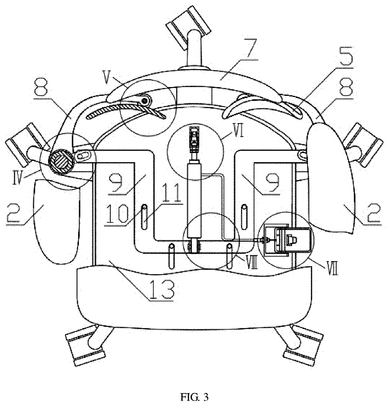
[0098]As shown in FIG. 1, FIG. 2, FIG. 3, FIG. 7, FIG. 8, FIG. 9, FIG. 10, FIG. 11, FIG. 12, FIG. 13 and FIG. 14, a chair with a backrest that may closely fit with the back of the human body to move, comprising a chair leg assembly 1, a seat cushion 3, an armrest assembly 4 and a backrest 5. A rocker arm 8 is arranged on upper part of the casing 6 of the armrest assembly 4; a pivot pin 32 movably connected with the rear part of the backrest 5 is arranged on the front end of the rocker arm 8; a bottom plate 13 is fixed to the lower part of the seat cushion 3; the lower part of the bottom plate 13 is fixedly connected to the upper part of the chair leg assembly 1; a control rack 31 fixed at rear part in the bottom plate 13 is connected with the front part of a gas rod 12; a connecting pin 33 connected to one end of the connecting arm I 9 is arranged at tail of the gas rod 12; an oscillating pin 17 movably embedded in the oscillating groove 18 at the lower part of the casing 6 is arran...
embodiment 2
[0107]As shown in FIG. 4, FIG. 5, FIG. 6, FIG. 7, FIG. 8, FIG. 9, FIG. 10, FIG. 12, FIG. 13, FIG. 14 and FIG. 15, a chair includes a chair leg assembly 1, a seat cushion 3, an armrest assembly 4 and a backrest 5. A rocker arm 8 is arranged on upper part of the casing 6 of the armrest assembly 4; a pivot pin 32 movably connected with the rear part of the backrest 5 is arranged on the front end of the rocker arm 8; a bottom plate 13 is fixed to the lower part of the seat cushion 3; the lower part of the bottom plate 13 is fixedly connected to the upper part of the chair leg assembly 1; a control rack 31 fixed at rear part in the bottom plate 13 is connected with the front part of a gas rod 12; a connecting pin 33 connected to one end of the connecting arm I 9 is arranged at tail of the gas rod 12; an oscillating pin 17 movably embedded in the oscillating groove 18 at the lower part of the casing 6 is arranged on another end of the connecting arm I 9.
[0108]The backrest 5 is a monoblock...
embodiment 4
[0125]As shown in FIG. 18, FIG. 19 and FIG. 20, the difference between Embodiment 4 and Embodiment 3 also lies in the specific structure of the transmission part 40. In Embodiment 4, the transmission part 40 includes a connecting piece 46 connected with the gas spring 12, a roller 44 connected to the connecting piece 46, a drawn wire 45 located in a wheel groove of the roller 44, and a rotating arm 47 connected with the rotating shaft assembly; the drawn wire 45 is connected with the rotating arm 47. The rotating arm 47 is provided with a wiredrawing head bayonet 48; the drawn wire 45 is connected with the wiredrawing head bayonet 48.
[0126]The coordination between the drawn wire 45 and the roller 44 is another specific embodiment of the transmission part 40. Specifically, the forward-moving gas spring 12 drives the connecting piece 46 to move forward; the connecting piece 46 may be connected with the roller 44 through fixtures such as a pin. A roller 44 is connected to the connectin...
PUM
 Abstract
Description
Claims
Application Information
 - R&D
- Intellectual Property
- Life Sciences
- Materials
- Tech Scout
- Unparalleled Data Quality
- Higher Quality Content
- 60% Fewer Hallucinations
Browse by: Latest US Patents, China's latest patents, Technical Efficacy Thesaurus, Application Domain, Technology Topic, Popular Technical Reports.
© 2025 PatSnap. All rights reserved.Legal|Privacy policy|Modern Slavery Act Transparency Statement|Sitemap|About US| Contact US: help@patsnap.com


