This helps you quickly interpret patents by identifying the three key elements:
Problems solved by technology
Method used
Benefits of technology
Benefits of technology
[0011] One or more embodiments of the present invention provide a projector-type vehicle headlamp in which an additional lens disposed on an outer periphery of a projection lens can be disposed along a surface shape of a projection lens so as to improve an appearance of the headlamp and a quantity of the light passing through the additional lens is not excessively increased.
Problems solved by technology
However, since the additional lens of the vehicle headlamp disclosed in JP-A-2002-358806 is composed of an annular lens that is formed to have a cross-section of a general plano-convex lens, there has been a problem that it is not possible to dispose the additional lens continuously along a surface shape of the projection lens.
If the light passing through the additional lens is intense, the headlamp causes glare to the driver of the oncoming vehicle.
Method used
Image
Click on the blue label to locate the original text in one second.
Reading with bidirectional positioning of images and text.
Examples
first exemplary embodiments
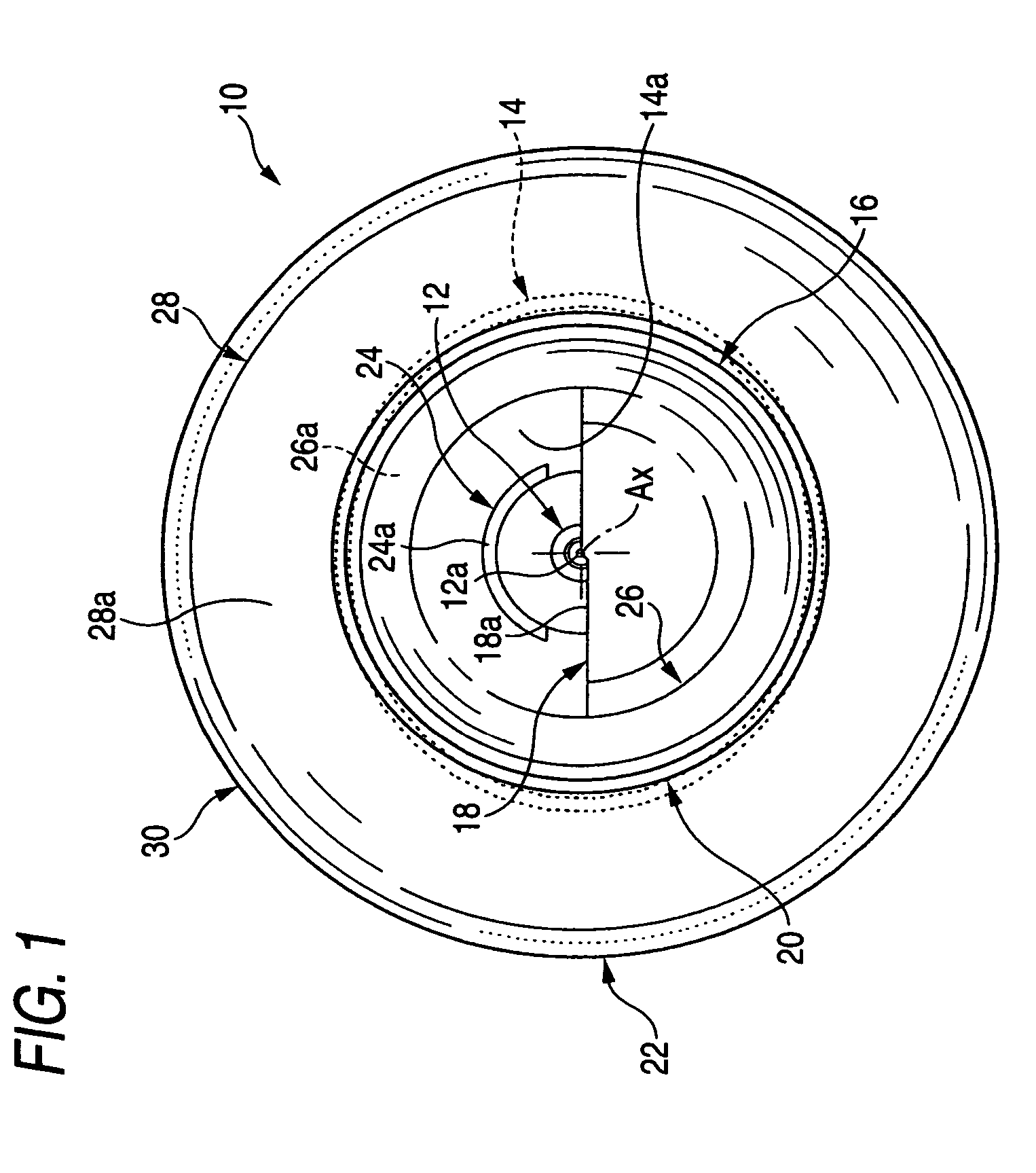
[0084]FIG. 1 is a front view of a vehicle headlamp 10 according to the first exemplary embodiment,
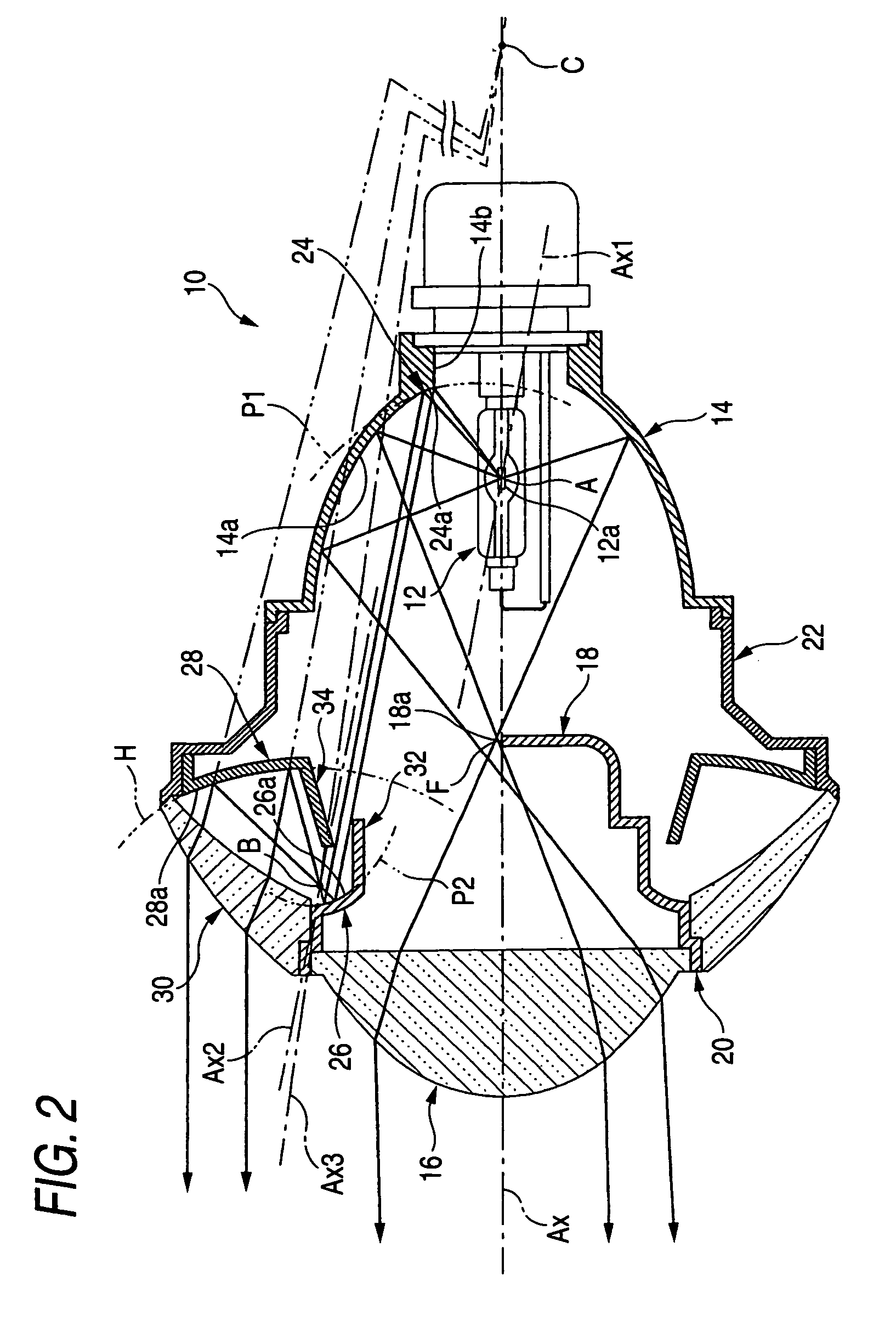
[0085]FIG. 2 is a side cross-sectional view thereof, and
[0086]FIG. 3 is a plan cross-sectional view thereof.
[0087] As shown in FIGS. 1 to 3, the vehicle headlamp 10 according to the first embodiment is composed of a projector-type lamp unit, which radiates light to form a low-beam light distribution pattern, and is used in a state in which the vehicle headlamp is assembled in a lamp body (not shown).
[0088] The vehicle headlamp 10 includes a light source bulb 12, a reflector 14, a projection lens 16, a shade 18, a first holder 20, a second holder 22, a first additional reflector 24, a second additional reflector 26, a third additional reflector 28, an additional lens 30, a first light-shielding member 32, and a second light-shielding member 34. In addition, the vehicle headlamp has an optical axis Ax extending in a longitudinal direction of a vehicle. However, when adjustment of the ...
second exemplary embodiment
[0122] A second exemplary embodiment of the invention will be described.
[0123]FIG. 5 is a side cross-sectional view showing a vehicle headlamp 110 according to a second exemplary embodiment of the invention.
[0124] As shown in FIG. 5, the basic structure of the vehicle headlamp 110 is entirely the same as that in the first exemplary embodiment, and the surface shapes of the reflection surfaces 124a and 126a of the first and second reflectors 124 and 126 are different from those of the first and second reflectors 24 and 26 of the vehicle headlamp 10 according to the first exemplary embodiment.
[0125] That is, the cross-section, which is taken along the plane including the optical axis Ax, of the reflection surface 124a of the first additional reflector 124 of the present exemplary embodiment is formed in the shape of a first ellipse E1, which uses the emission center of the light source 12a as a first focal point and uses a point D disposed on the front side of the first additional ...
third exemplary embodiment
[0129] A third exemplary embodiment of the invention will be described.
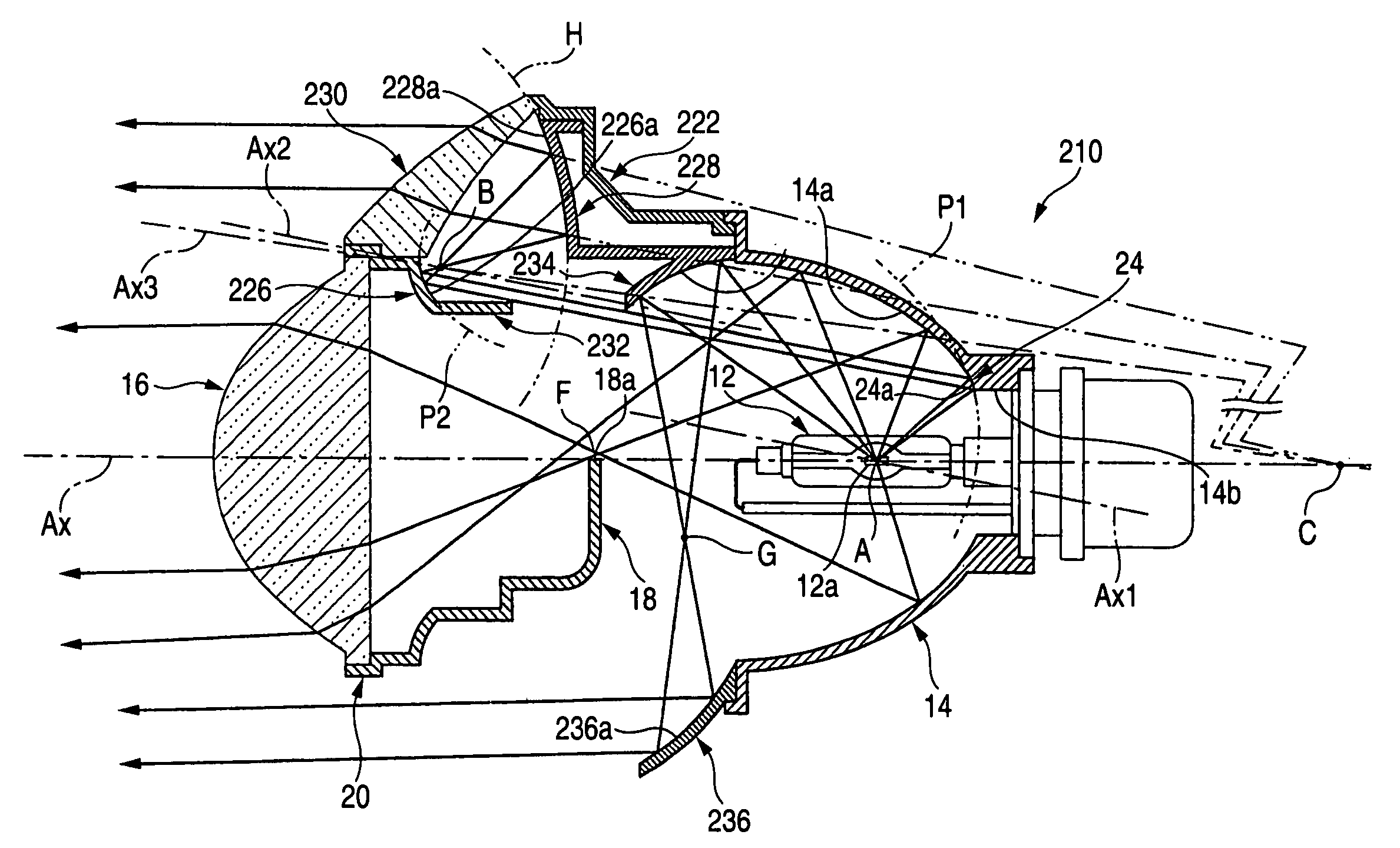
[0130]FIG. 6 is a front view of a vehicle headlamp 210 according to a third exemplary embodiment of the invention, and FIG. 7 is a side cross-sectional view thereof.
[0131] As shown in FIGS. 6 and 7, the basic structure of the vehicle headlamp 210 is entirely the same as that in the first exemplary embodiment, and the structure of a second light-shielding member 234 is different from that of the vehicle headlamp 10 according to the first exemplary embodiment.
[0132] That is, the second light-shielding member 234 of the third exemplary embodiment is composed of a fourth additional reflector, which is provided on the front-upper side of the light source 12a and reflects the direct light emitted from the light source 12a toward the lower side. The front edge of the second light-shielding member 234 prevents the light other than the light, which is emitted from the light source 12a and is then reflected by the first...
PUM
Abstract
Light emitted from a light source 12a is sequentially reflected on a first, second, and third additional reflectors in this order. By emitting light in the order of the reflectors, this allows the light to be parallel to an optical axis by an additional lens. Accordingly, it is possible to increase the light-emitting area of the entire headlamp, thereby improving the appearance of the headlamp with respect to the driver of the oncoming vehicle. The additional lens is formed to have a substantially wedge-shaped cross-section, and is provided along the surface shape of a projection lens. Furthermore, since the light emitted from the light source is sequentially reflected by the first, second, and third additional reflectors in this order, the light emitted from the light source can be focused and the quantity of the light passing through the additional lens is not excessively increased.
Description
[0001] The present application claims foreign priority based on Japanese Patent Application No. P.2005-145546, filed on May 18, 2005, the contents of which are incorporated herein by reference. BACKGROUND OF THE INVENTION [0002] 1. Field of the Invention [0003] The present invention relates to a projector-type vehicle headlamp. [0004] 2. Related Art [0005] A projector-type vehicle headlamp is generally provided with a projection lens disposed on an optical axis extending in a longitudinal direction of a vehicle, and a light source disposed on a rear side of a rear focal point of the projection lens, and light emitted from the light source is reflected by a reflector toward the optical axis. [0006] Disclosed in JP-A-2002-358806 is a projector-type vehicle headlamp provided with an annular additional lens on an outer periphery of the projection lens so that the light emitted from the light source passes through the additional lens travels toward a front side thereof substantially para...
Claims
Application Information
Patent Timeline
Application Date:The date an application was filed.
Publication Date:The date a patent or application was officially published.
First Publication Date:The earliest publication date of a patent with the same application number.
Issue Date:Publication date of the patent grant document.
PCT Entry Date:The Entry date of PCT National Phase.
Estimated Expiry Date:The statutory expiry date of a patent right according to the Patent Law, and it is the longest term of protection that the patent right can achieve without the termination of the patent right due to other reasons(Term extension factor has been taken into account ).
Invalid Date:Actual expiry date is based on effective date or publication date of legal transaction data of invalid patent.

