
Wearable article having a backlit lenticular display

Inactive Publication Date: 2006-11-09
WELCH STEPHEN R
View PDF17 Cites 17 Cited by
  • Summary
  • Abstract
  • Description
  • Claims
  • Application Information

AI Technical Summary

Benefits of technology

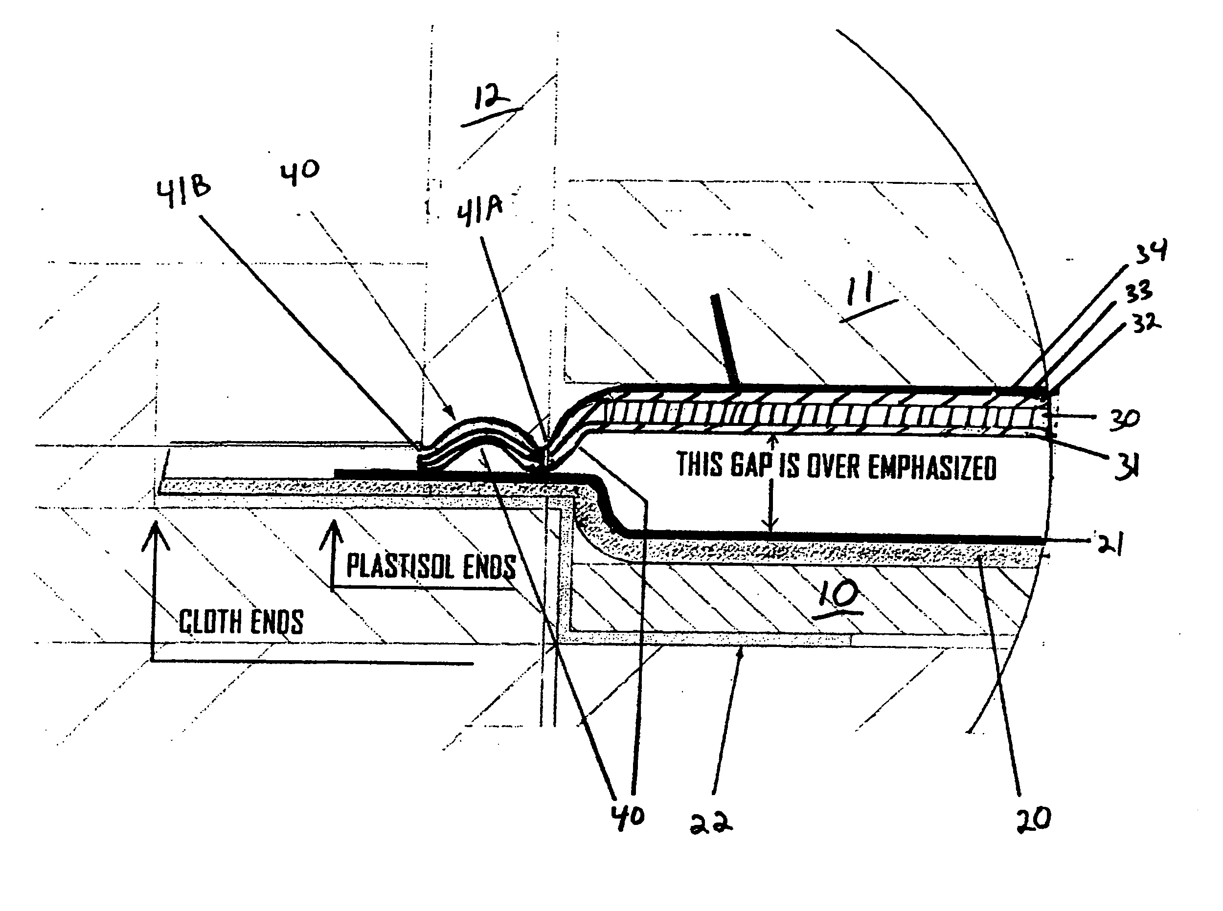
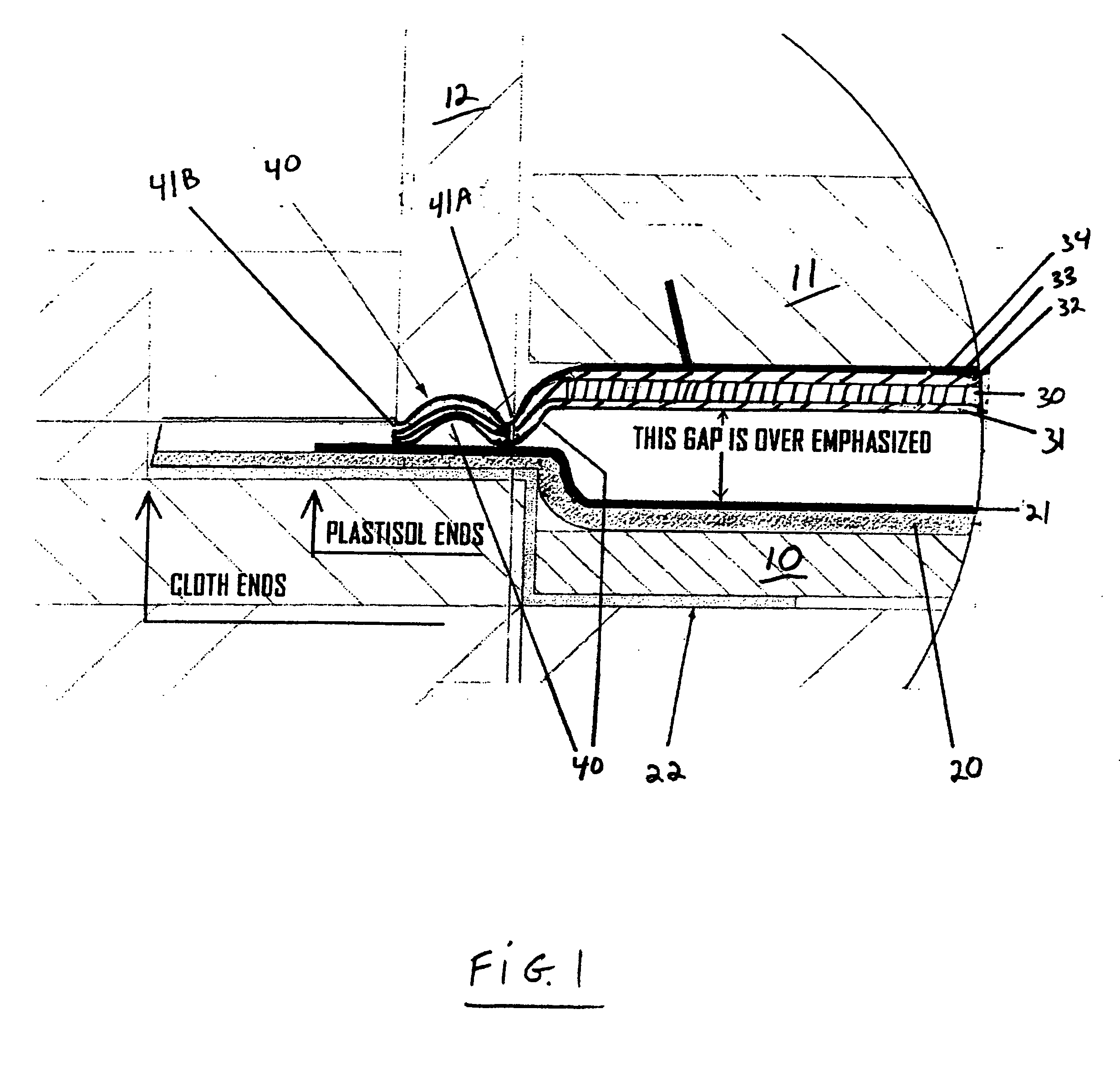
[0010] The present invention relates to a lenticular display device, and in particular to a combination comprising a wearable article that has a backlit lenticular assembly associated therewith, the backlit lenticular assembly comprising a lenticular, an electroluminescent panel for providing backlight, and an image(s) provided between the lenticular and electroluminescent panel, wherein the backlight illuminates the image(s) to provide greater visibility and an enhanced appearance to the image. The image(s) may be provided on either the lenticular, electroluminescent panel, or on a removable support member that is placed between the lenticular and electroluminescent panel.
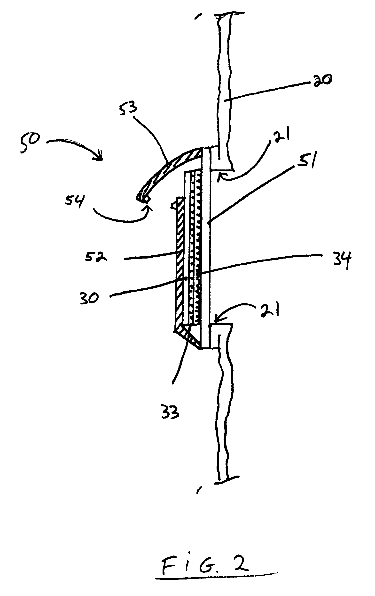
[0013] In another embodiment of the invention, the article may include a compartment and the lenticular, image(s), and electroluminescent lamp of the display device is placed in the compartment. It is desirable for the compartment to have a transparent viewing window adjacent the lenticular and the image(s) is provided on a support and in a manner that facilitates removal and replacement of the image(s) and support. In the preferred arrangement, the image(s) are adhered to the support with an optically clear adhesive so that it is removable with the lenticular.
[0018] An alternative method of preparing the combination comprises forming a compartment in or on the article and inserting into the compartment a lenticular, an electroluminescent panel for providing backlight, and an image(s) provided between the lenticular and electroluminescent panel. The backlight serving to illuminate the image(s) to provide greater visibility and an enhanced appearance to the image. In this embodiment the image(s) may be affixed to the lenticular, the electroluminescent panel, or to a support which is removably attached to the assembly. Preferably, this method further comprises forming the lenticular, image(s), and electroluminescent panel as an integral unit, which is removably contained in the compartment. Further, the compartment may be radio frequency welded to the bonding material. Ideally, the compartment is formed with a transparent viewing window adjacent the lenticular.

Problems solved by technology

Electrical signs, however, are often very costly, bulky, generate undesired heat, and are difficult to repair.
Further, electrical signs are also not practical for packages, clothing, etc.
A common method of attaching the image to the lenticular is with the use of adhesives, however this configuration is undesirable in that it is prone to distortion of the image.
This results in ghosting or crosstalk distortion between the images, which is a phenomenon that occurs when the viewer sees two or more images at the same time from a single viewpoint of a lenticular image.
As a result, the effectiveness of the display device is limited to conditions where sufficient ambient light is available, and directed towards the image.
Such a limitation is particularly undesirable for a garment lenticular wherein the positioning of the lenticular, materials, and color of the garment itself may diminish the available ambient light.
However, the fasteners disclosed are disadvantageous because they are subject to damage, and fail to provide a sufficient bond to withstand extended use.
Further, a drawback of the use of EL lamps is that they are susceptible to moisture damage, and this can occur when the garment becomes wet such as from being in the rain or if a liquid is spilled on it.

Method used


Image

  • Wearable article having a backlit lenticular display
  • Wearable article having a backlit lenticular display
  • Wearable article having a backlit lenticular display

Examples


Embodiment Construction

[0023] The present invention relates to a display device for displaying one or more removable images or through a lenticular lens, and in particular, to a lenticular lens having an electroluminescent light source, attached to a wearable article such as a garment.

[0024] According to a preferred embodiment of the present invention, a backlit lenticular display device is adapted for use with apparel by printing images within a lenticular display device having a electroluminescent panel providing enhanced visual and optical characteristics and decorative appeal, and affixing the lenticular display device onto a fabric substrate. More particularly, the invention relates to a method, and an article formed by that method, of printing optical images possessing depth of field, i.e., three-dimensional and / or the appearance of motion, i.e., animated imagery in communication with a lenticular sheet, incorporating an electroluminescent light source, and bonding such a device to an article such ...


PUM

PropertyMeasurementUnit
Electrical resistanceaaaaaaaaaa
Transparencyaaaaaaaaaa
Electroluminescenceaaaaaaaaaa

Abstract

The present invention provides a wearable article such as clothing, backpacks, hats, and the like that include a backlit lenticular lens display that emits light to allow animation and special effects. The array of interlaced images can be printed directly onto the electroluminescent panel, onto a removable support sheet, or onto the back surface of the lenticular. The electroluminescent panel is laminated to form a flange portion that is radio frequency welded to bond the lenticular display device to an article that is impregnated with a bonding material. A backing material having a fabric layer and a water impenetrable layer can be affixed to the assembly such that the fabric layer contacts the skin. Alternatively, the article may have a surface a display compartment or envelope with a transparent outer surface for enclosing the electroluminescent layer, a removable image sheet, and a lenticular lens layer.

Description

[0001] This application claims the benefit of U.S. provisional application 60 / 738,346 filed Nov. 18, 2005 and 60 / 678,366 filed May 7, 2005, the entire content of each of which is expressly incorporated herein by reference thereto.BACKGROUND OF THE INVENTION [0002] This invention pertains to wearable articles such as clothing, backpacks, hats, and the like that include visual displays thereon, and more particularly, to such articles that include advertising and decorative displays that utilize lenticulars and that are provided with electroluminescent lamp illumination. [0003] Conventional print advertising and packaging is accomplished by printing stationary non-moveable information and pictures on magazines, posters, billboards, signs, clothing, etc. A primary purpose of an advertisement is to attract the attention of the reader (customer) and convey the desired information. [0004] In an effort to attract the customer's attention, various types of electrical signs have been installe...

Claims


Application Information

Patent Timeline
IPC IPC(8): G02B5/12
CPCA41D27/085H04N2213/001H04N13/0404G09F21/02H04N13/305
Inventor WELCH, STEPHEN R.
Owner WELCH STEPHEN R
Learn More