Liquid crystal display element

A technology of liquid crystal display elements and liquid crystal layers, applied in static indicators, optics, instruments, etc., can solve problems such as poor display and achieve excellent visual recognition

Active Publication Date: 2007-07-18
STANLEY ELECTRIC CO LTD
View PDF2 Cites 3 Cited by
  • Summary
  • Abstract
  • Description
  • Claims
  • Application Information

AI Technical Summary

Problems solved by technology

But even with this approach, some display artifacts can occur

Method used


Image

  • Liquid crystal display element
  • Liquid crystal display element
  • Liquid crystal display element

Examples


no. 1 example

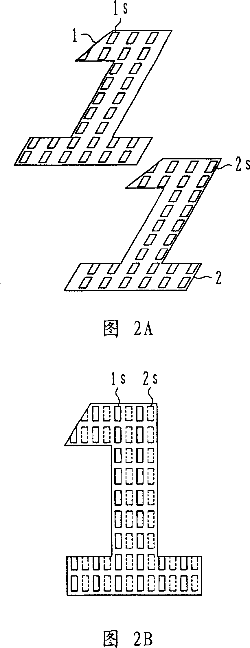
[0081] FIG. 8 shows an example of a two-region TN-LCD having a segment structure. The structure of the TN-LCD shown in FIG. 8 is that upper segment electrodes 6 and lower common electrodes 7 representing numbers "1" and "2" sandwich liquid crystal as a pair of electrodes. In this example, the conduction range of the segment electrode 6 is narrowed, and the conduction range of the common electrode 7 is widened.

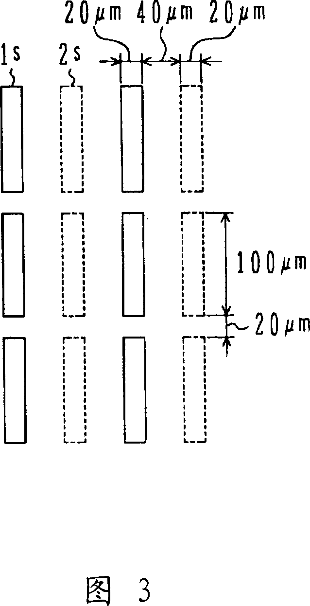
[0082] The segment electrode 6 and the common electrode 7 are provided with rectangular slits 6 s and 7 s with a part removed. The slits 6s provided on the segment electrodes and the slits 7s provided on the common electrode are arranged alternately in the short direction of the slits. In addition, the number of divisions per unit length of the slit provided on one electrode is different from that of the slit provided on the other electrode. Here, the number of divisions refers to the number of separation positions in the longitudinal direction of the slit, and when ...

no. 2 example

[0098] A vertical alignment type LCD of a second embodiment will be described. Briefly, the two-region vertical alignment type LCD of the second embodiment is an LCD of the same structure and material as those of the second comparative example, and its slit pattern is the same as that of the first embodiment.

[0099] When a voltage was applied to the cell to display the liquid crystal cell, no display unevenness was observed even when the liquid crystal cell was viewed from an oblique direction. Furthermore, even after 1000 hours had elapsed after the cell was continuously energized in an atmosphere of 85° C., display failure did not occur.

no. 3 example

[0101] The case of a simple matrix type two-region TN-LCD and a two-region vertical alignment type LCD will be described with reference to FIG. 10 . Fig. 10 is a plan view of a simple matrix liquid crystal display element of the present invention.

[0102] Similar to the segment display, the liquid crystal cell used in the third embodiment, as shown in FIG. 10 , has a structure in which the upper segment electrode 15 and the lower common electrode 16 serve as a pair of electrodes sandwiching the liquid crystal. The segment electrodes 15 and the common electrode 16 are provided with rectangular slits 15 s and 16 s with a part removed. The slits 15s provided on the segment electrodes 15 and the slits 16s provided on the common electrode 16 are alternately arranged in the short direction of the slits. Furthermore, the number of divisions per unit length of the slit provided on one electrode is different from that of the slit provided on the other electrode, and the slit with a s...


PUM


Abstract

The invention relates to a liquid crystal display element capable of increasing viewing angle characteristics and preventing poor display. The produced liquid crystal display element comprised: a first substrate and a second substrate opposite to each other; a first transparency electrode and a second transparency electrode disposed on the opposite surfaces of the first substrate and the second substrate, which form a defined graph for displaying and are opposite with each other, separated by a clearance; a liquid crystal layer held by the first substrate and the second substrate; and a plurality of apertures disposed on the first transparency electrode and the second transparency electrode, respectively, and in the same direction. The aperture includes: a first aperture arranged on the first substrate in a matrix manner, and a second aperture arranged on the second substrate in a matrix manner parallelly to the first aperture, wherein the first aperture and the second aperture are alternately provided in a short direction, and length of the second aperture is longer than that of the first aperture.

Description

technical field [0001] The present invention relates to a liquid crystal display element, in particular to a liquid crystal display element which prevents display defects. Background technique [0002] In recent years, a method of using a slit to improve the viewing angle characteristics of a liquid crystal display element has been proposed. When a slit is formed on one of the upper and lower opposing electrodes disposed across the liquid crystal layer, the lines of force generated from the portion of the other electrode facing the slit must be terminated at the electrodes on both sides of the slit, thereby generating an oblique disturbance electric field. When the slits are alternately formed on the upper and lower electrodes, it is possible to realize alignment of the liquid crystal molecules in a region between the upper and lower slits. A liquid crystal display element using a slit is disclosed in the following patent documents. [0003] Patent Document 1: Patent No. 3...

Claims


Application Information

Patent Timeline
Patent Type & Authority Applications(China)
IPC IPC(8): G02F1/1333G02F1/1343G02F1/133G09F9/35
Inventor 杉山贵岩本宜久
Owner STANLEY ELECTRIC CO LTD
Why Eureka
Try Eureka