Transflective liquid crystal display with backlight and reflection film

Inactive Publication Date: 2005-02-08
ONANOVICH GROUP
View PDF16 Cites 3 Cited by
  • Summary
  • Abstract
  • Description
  • Claims
  • Application Information

AI Technical Summary

Benefits of technology

In such a construction, it is possible to obtain a liquid crystal display having superior visibil

Problems solved by technology

Therefore, the propagation loss of light is increased, and it is not possible to obtain satisfactory brightness when the transflective liquid crystal display 100 is used as a reflective liquid crystal display.
Therefore, it is not possible to sufficiently increase the aperture ratio,

Method used


Image

  • Transflective liquid crystal display with backlight and reflection film
  • Transflective liquid crystal display with backlight and reflection film
  • Transflective liquid crystal display with backlight and reflection film

Examples


first embodiment

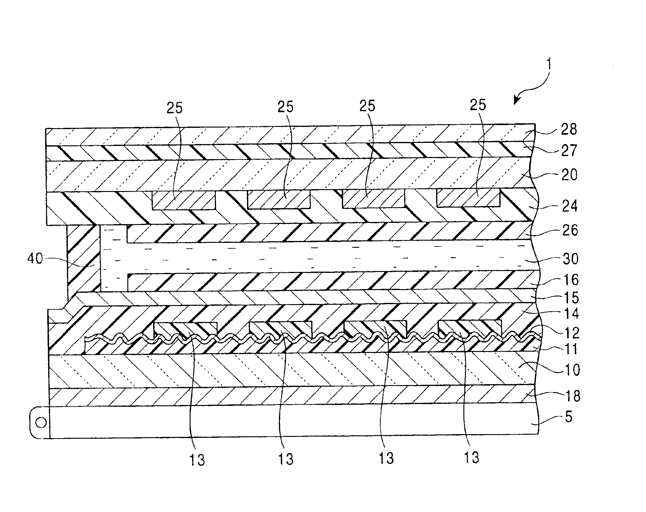
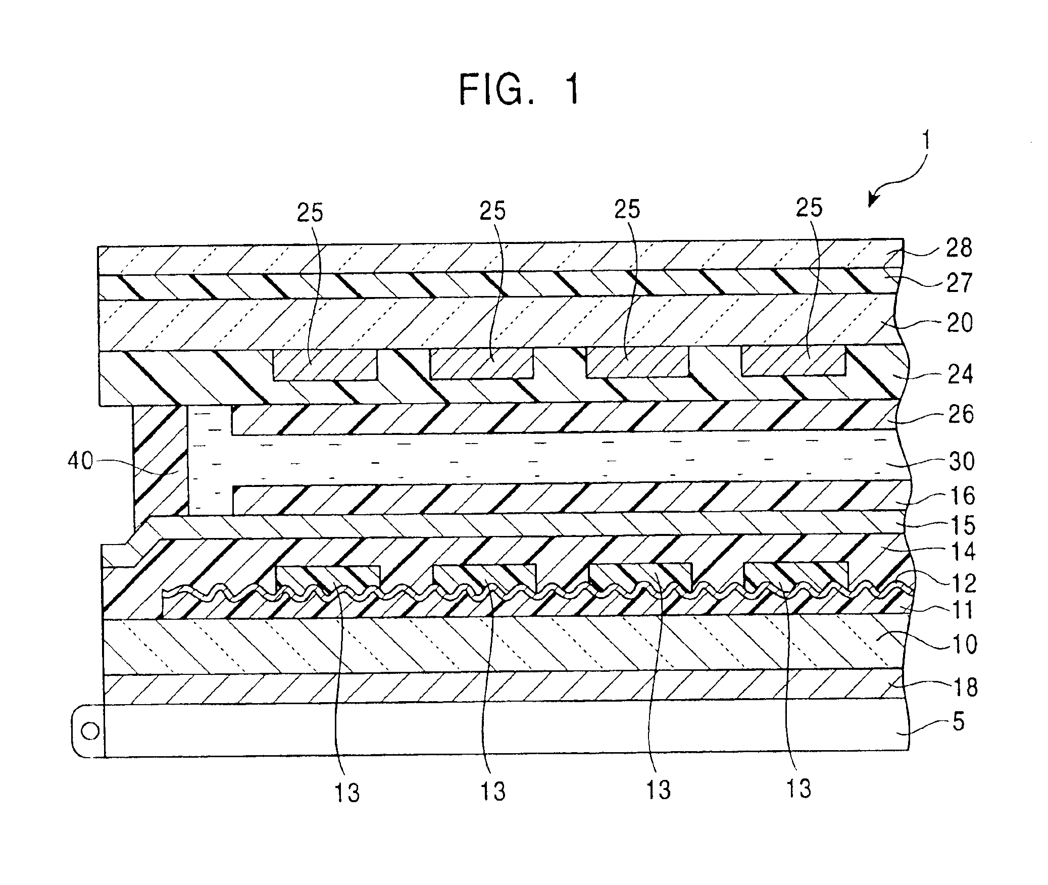
FIG. 1 is a partial sectional view which schematically shows a transflective liquid crystal display including an edge thereof in a first embodiment of the present invention. As shown in FIG. 1, in a transflective liquid crystal display 1, a first substrate 10 and a second substrate 20, for example, composed of a transparent glass, which oppose each other with a liquid crystal layer 30 therebetween, are integrally bonded to each other by a sealant 40 which is annularly provided in the periphery of the two substrates 10 and 20.

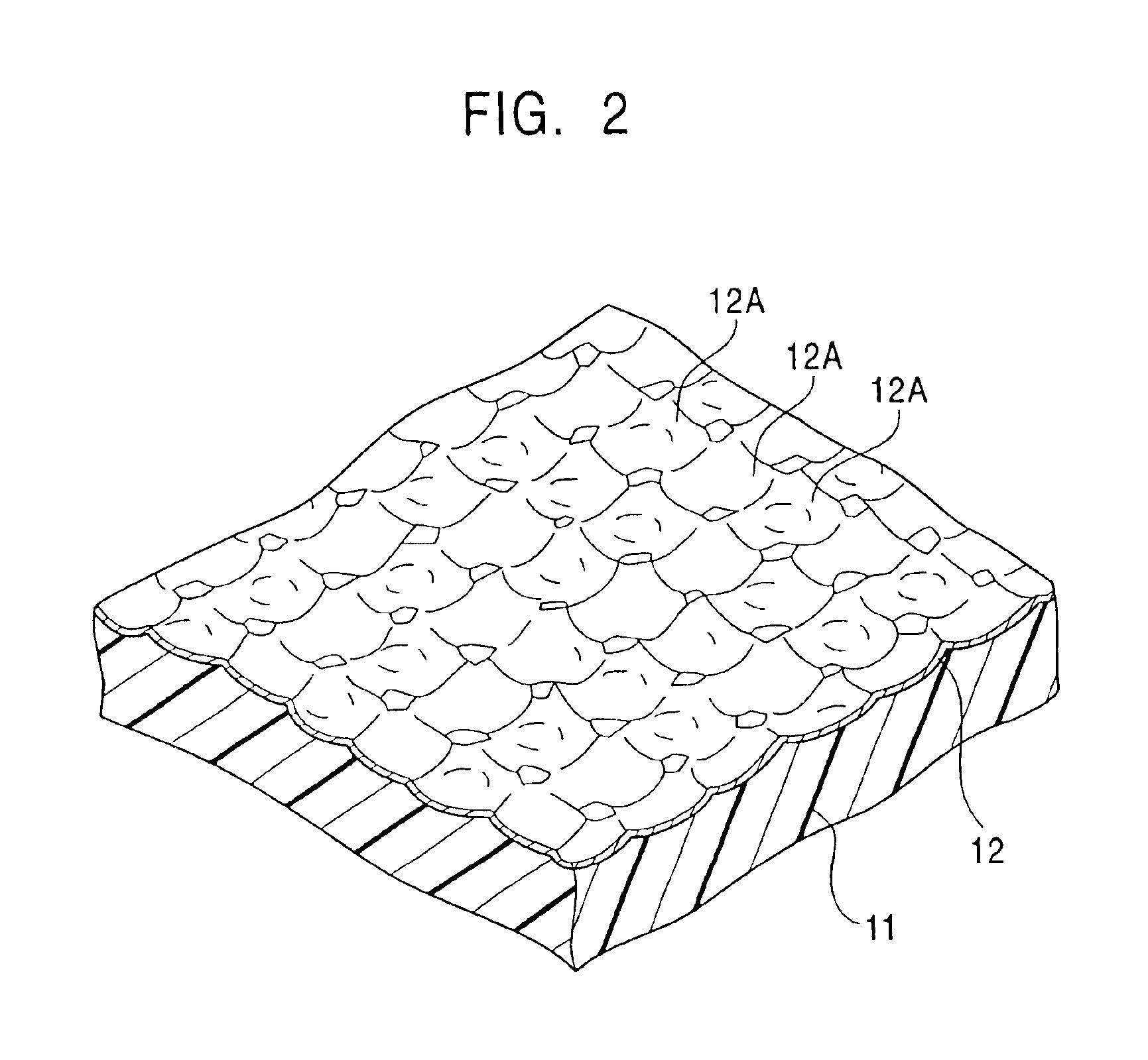
At the liquid crystal layer 30 side of the first substrate 10, an organic film 11 for corrugating a reflection film 12, a metallic reflection film 12 for reflecting light entering the liquid crystal display, color filters 13 for performing color display, an overcoat film 14 for protecting the organic film 11 and the metallic reflection film 12 as well as for planarizing the corrugation due to the organic film 11 and the color filters 13, electrode layers 15 for ...

second embodiment

In the first embodiment, the metallic reflection film 12 for reflecting light entering from outside is disposed between the substrate 10 and the substrate 20. In contrast, in a second embodiment of the present invention, a reflector is provided on the exterior of two substrates which sandwich a liquid crystal layer.

FIG. 4 is a partial sectional view which schematically shows a liquid crystal display 2 in the second embodiment of the present invention. As shown in FIG. 4, in the liquid crystal display 2, a first substrate 60 and a second substrate 70, for example, composed of a transparent glass, which oppose each other with a liquid crystal layer 80 therebetween, are integrally bonded to each other by a sealant 90 which is annularly provided in the periphery of the substrates 60 and 70.

At the liquid crystal layer 80 side of the first substrate 60, electrode layers 65 for driving the liquid crystal layer 80, and an alignment film 66 for controlling the alignment of liquid crystal mol...

example 1

An organic film composed of a photosensitive resin having a thickness of 2 μm was formed on a glass substrate with a thickness of 0.7 mm. An aluminum film, as a metallic reflection film, was deposited on the organic film at a thickness of 90 Å, and an overcoat film was deposited at a thickness of 300 Å so as to cover the organic film and the metallic reflection film. Electrode layers and an alignment film were deposited thereon in that order, and a substrate for a liquid crystal display was thereby prepared. With respect to the surface configuration of the organic film, concaves were formed on the surface of the organic film so as to satisfy the following conditions: the depth of the concave portions was in the range of 0.6 to 1.2 μm, the inner surface of each concave portion constituting a part of a spherical surface; the inclination angle of the inner surface of each concave portion was in the range of −8 degrees to +8 degrees; and the pitch of the adjoining concave portions was i...


PUM


Abstract

A liquid crystal display includes a pair of substrates which oppose each other with a liquid crystal layer therebetween; a light source provided on the exterior of one of the substrates; and at least an organic film, a metallic reflection film, an overcoat film, an electrode layer, and an alignment film formed on the inner face of one of the substrates. Many concaves are contiguously formed on a surface of the organic film, the inner surface of each concave constituting a part of a spherical surface. The metallic reflection film has a thickness of 80 to 500 Å. A transflector and a liquid crystal display including the transflector are also disclosed.

Description

BACKGROUND OF THE INVENTION1. Field of the InventionThe present invention relates to liquid crystal displays and, more particularly, to a technique suitable for use in a transflective liquid crystal display provided with a backlight and a reflection film.2. Description of the Related ArtSubstantially all mobile phones and mobile information terminals are now provided with liquid crystal displays, and recently, many such mobile electronic apparatuses have been provided with transflective liquid crystal displays.In general, a transflective liquid crystal display includes a reflector provided on the interior or exterior of a pair of transparent substrates for reflecting incident light from outside and also includes a backlight at the back side thereof. The transflective liquid crystal display can be used as a reflective liquid crystal display and as a transmissive liquid crystal display by switching between a reflective mode in which solar light or an external illumination is used as a...

Claims


Application Information

Patent Timeline
IPC IPC(8): G02F1/1335G02F1/13G02B5/08G02F1/1333
CPCG02F1/133555G02F1/1335
Inventor TANADA, TETSUSHIOHIZUMI, MITSUOKANO, MITSURU
Owner ONANOVICH GROUP
Why Eureka
Try Eureka