
Camera and electronic apparatus

A technology for electronic equipment and cameras, which is applied to cameras, camera bodies, televisions, etc., can solve problems such as increasing the lens driving load, and achieve the effect of improving appearance

Inactive Publication Date: 2005-08-24
OLYMPUS CORP
View PDF5 Cites 17 Cited by
  • Summary
  • Abstract
  • Description
  • Claims
  • Application Information

AI Technical Summary

Problems solved by technology

[0005] Regarding the waterproofing of the camera, the original waterproofing adopts a structure that seals the inside from the outside of the device. When the lens arranged inside the camera is driven, due to the movement of the lens, there will be an air pressure difference between the inside and outside of the camera, and the air pressure difference will be Increase the driving load of the lens

Method used


Image

  • Camera and electronic apparatus
  • Camera and electronic apparatus
  • Camera and electronic apparatus

Examples


Embodiment 1

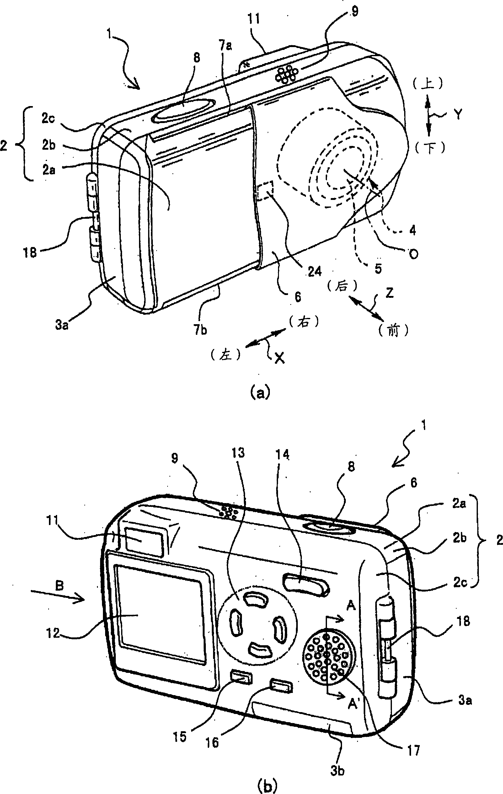
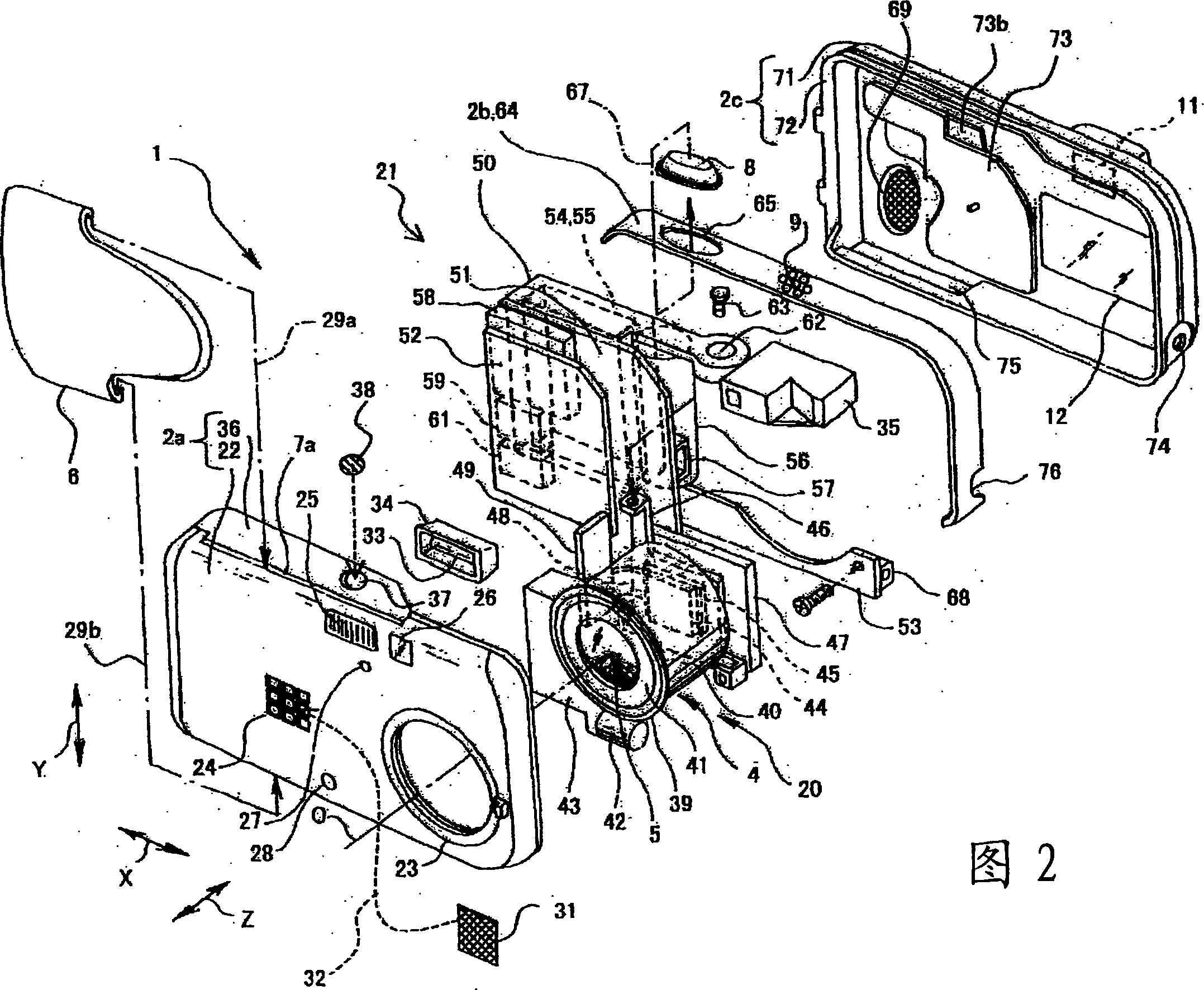
[0155] figure 1 (a) is a perspective view of the appearance of the digital camera according to the first embodiment viewed from the front. figure 1 (b) is an external perspective view seen from the back. In addition, in the description of the arrangement diagram of the digital camera 1 of this embodiment, the camera width direction, that is, the left-right direction indicated by the double-headed arrow X in the figure, is the left-right direction viewed from the subject side of the camera. In addition, in the direction of the photographing optical axis O of the lens, the front and rear direction of the camera represented by the double-headed arrow Z in the figure refers to the side of the subject as the front, and the side opposite to the subject as the rear or back side. . In addition, the up-down direction indicated by the double-headed arrow Y in the figure indicates the up-down direction when the camera is held in the normal state.

[0156] Such as figure 1 (a), figur...


PUM


Abstract

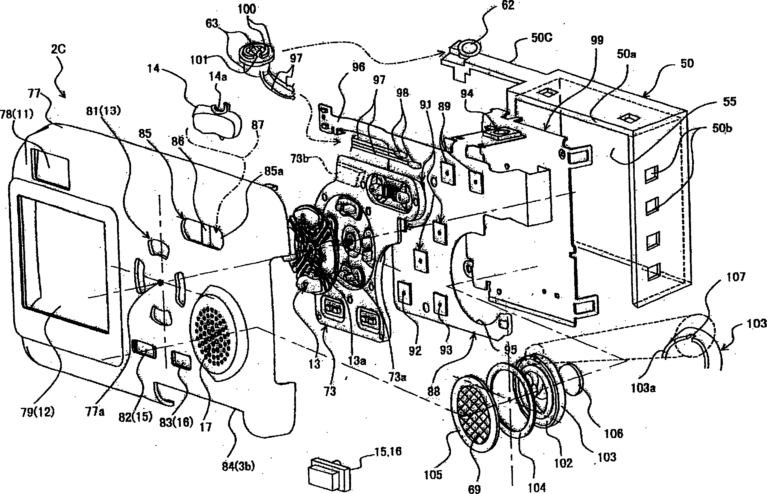
The objective of the invention is to provide a camera or an electronic instrument having an inconspicuous air hole compromising no external appearance in the armor section of a main body and in which a microphone and a speaker recording and reproducing a voice are placed at positions allowing easy use for the microphone and the speaker in the armor section of the main body. The back of the speaker frame 109 of the speaker 102 is brought into intimate contact with a plate-like member 99 through a cushion 106 and a pressure sensitive adhesive double coated sheet 111. A speaker diaphragm 108 is shielded from the interior space 113 of the camera by a flange 103, a hard spacer 104, a waterproof sheet 69 for speaker, and a pressure sensitive adhesive double coated tape 105. Meanwhile, the use of a small notch 107 formed on part of the flange 103 installs the speaker 102 on the waterproof sheet 69 for speaker in such a way that a speaker vibration cone 108-including space 112 may partially communicate with the internal space 113 of the camera. The waterproof sheet 69 for speaker has moisture interruption and air transmission. The interior space 113 of the camera air-communicates with the external space 114 of the camera through the waterproof sheet 69 for speaker, the speaker vibration cone 108-including space 112, and the notch 107 of the flange 103.

Description

technical field [0001] The present invention relates to a camera or electronic equipment having a waterproof structure. Background technique [0002] Conventionally, there is known a waterproof stereo microphone which is embedded and fixed in a travel bag for accommodating a video camera, has stereo performance, is miniaturized, and has improved sensitivity. (For example, refer to Patent Document 1) [0003] Lifting the microphone is like lifting the loudspeaker. Generally, the microphone and the loudspeaker are used integrally. Like the above-mentioned microphone, as a loudspeaker with waterproof measures, such a piezoelectric sounder is known. When using a cordless phone or a mobile phone in an environment with splashes or high humidity, it can prevent the entry of water droplets or moisture, etc., and can reduce the deterioration of sound pressure caused by waterproof measures. (For example, refer to Patent Document 2) [0004] For waterproofing, it is not limited to t...

Claims


Application Information

Patent Timeline
IPC IPC(8): G03B15/03G03B11/04G03B15/05G03B17/02G03B17/04G03B17/08H04N5/225H04R1/00H04R1/44H04R17/00
CPCH04N5/2252H04R1/44H04N23/51
Inventor 藤井尚树金子薰铃木伸哉
Owner OLYMPUS CORP
Learn More