Distributed rc termination

a technology of rc termination and distribution, applied in the direction of resistors, electric devices, solid-state devices, etc., to achieve the effect of low resistivity, wide bandwidth, and constant resistance of resistive elements

Active Publication Date: 2020-05-14
MURATA MFG CO LTD
View PDF0 Cites 0 Cited by
  • Summary
  • Abstract
  • Description
  • Claims
  • Application Information

AI Technical Summary

Benefits of technology

[0006]The present invention provides a semiconductor device that integrates a capacitor and a resistive element in the same die. In an embodiment, the capacitor provides a decoupling capacitor and the resistive element provides a broadband damping resistor. Despite using a low resistivity substrate (which accommodates design considerations of the capacitor but not the resistive element), a substantially constant resistance for the resistive element can be maintained over a wide bandwidth. The low resistivity substrate ensures a good ground return path for the capacitor. With the semiconductor device configured to have a substantially constant impedance over a wide bandwidth, the device can be highly suited for use in impedance controlled circuits, such as termination circuits, for example.

Problems solved by technology

Conventionally, these two components are implemented as separate devices on separate substrates due to antagonistic requirements for substrate properties.

Method used


Image

  • Distributed rc termination
  • Distributed rc termination

Examples


example implementations

[0051 of embodiments are now described. These implementations are provided for the purpose of illustration only and are not limiting.

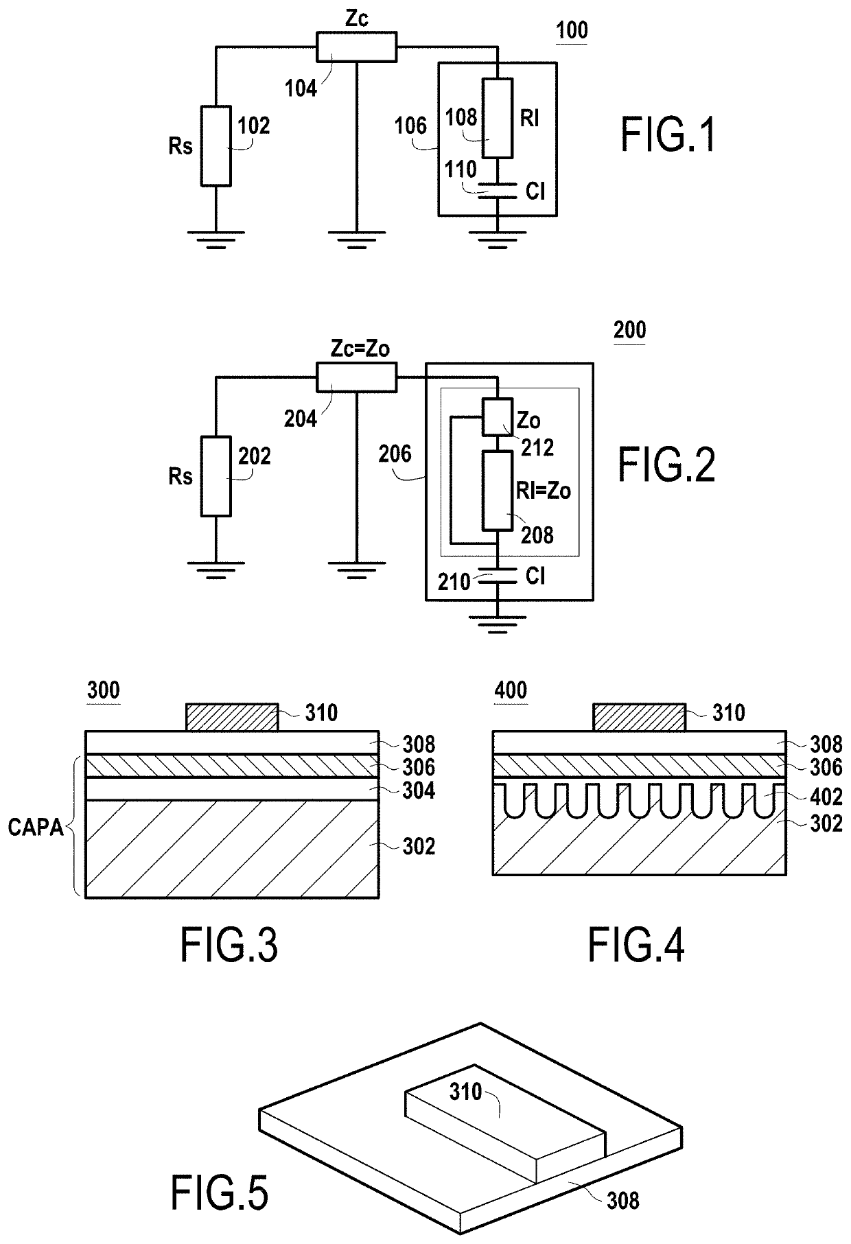
[0052]FIG. 3 illustrates a cross-section of an RC structure 300 according to an embodiment. In an embodiment, RC structure 300 forms an envelope termination circuit used in an RF power transmitter utilizing envelope injection. In an embodiment, RC structure 300 provides a decoupling capacitor and a broadband damping resistor.

[0053]As shown in FIG. 3, RC structure 300 includes a substrate 302, a first dielectric layer 304 disposed above substrate 302; a conductive layer 306 disposed above first dielectric layer 304; a second dielectric layer 308 disposed above conductive layer 306; and a resistive layer 310 disposed above second dielectric layer 308.

[0054]Substrate 302, first dielectric layer 304, and conductive layer 306 form a vertical capacitor, with conductive layer 306 providing the top capacitor plate and substrate 302 providing the bottom capacit...


PUM

PropertyMeasurementUnit
thicknessaaaaaaaaaa
thicknessaaaaaaaaaa
thicknessaaaaaaaaaa

Abstract

An integrated resistor-capacitor (RC) structure (400) is disclosed. The integrated RC structure includes a vertical capacitor (302,402,306) and a resistive element (308,310) disposed above the capacitor. The integrated RC structure uses a low ohmic substrate (302) to ensure a good ground return path for the capacitor. Further, a resistivity of the substrate is configured such that a top plate (306) of the capacitor provides a reference ground above a predefined frequency. The impedance of the resistive element (308,310) is matched, relative to the reference ground, to a predetermined resistance. As such, the resistance of the resistive element (308,310) can be controlled to provide an impedance controlled RC structure over a range of operating frequencies.

Description

CROSS REFERENCE TO RELATED APPLICATIONS[0001]The present application is a continuation of International application No. PCT / IB2018 / 000742, filed Jul. 16, 2018, which claims priority to European Patent Application No. 17305946.0, filed Jul. 17, 2017, the entire contents of each of which are incorporated herein by reference.FIELD OF THE INVENTION[0002]The present invention relates to integrated structures including resistive and capacitive elements.BACKGROUND OF THE INVENTION[0003]In various applications, for example in radio-frequency (RF) applications such as optical transceivers or RF power amplifiers, passive elements such as resistors and capacitors are often required. As the operating bandwidth continues to increase for these applications, reaching up to several GHz in some cases, it is desirable to control the behavior of the passive elements. Specifically, it is desirable to manage bandwidth limitations due to the passive elements to ensure a substantially constant frequency r...

Claims


Application Information

Patent Timeline
Patent Type & Authority Applications(United States)
IPC IPC(8): H01L27/07H01L27/06H01L29/66H01L29/94H01L49/02
CPCH01L27/0682H01L28/24H01L27/0794H01L28/40H01L29/66181H01L29/945H01L29/94H01L28/60
Inventor NORMAND, NICOLASBOUVIER, STÉPHANE
Owner MURATA MFG CO LTD
Why Eureka
Try Eureka