Automatic hair implant apparatus

a hair implant and automatic technology, applied in the field of automatic hair implant devices, can solve the problems of increasing patient and doctor fatigue, limited commercialization, and high cost of the abov

Inactive Publication Date: 2020-05-21
ELECTRONICS & TELECOMM RES INST
View PDF0 Cites 6 Cited by
  • Summary
  • Abstract
  • Description
  • Claims
  • Application Information

AI Technical Summary

Problems solved by technology

In the case of a manual follicle implanting device which is currently used, since roughly 2,000 follicles (graft) are involved in a single procedure on one patient, patient and doctor fatigue can increase.
Further, a procedure has no choice but to be long, and thus costs for the above are expensive and commercialization is limited.

Method used


Image

  • Automatic hair implant apparatus
  • Automatic hair implant apparatus
  • Automatic hair implant apparatus

Examples


first embodiment

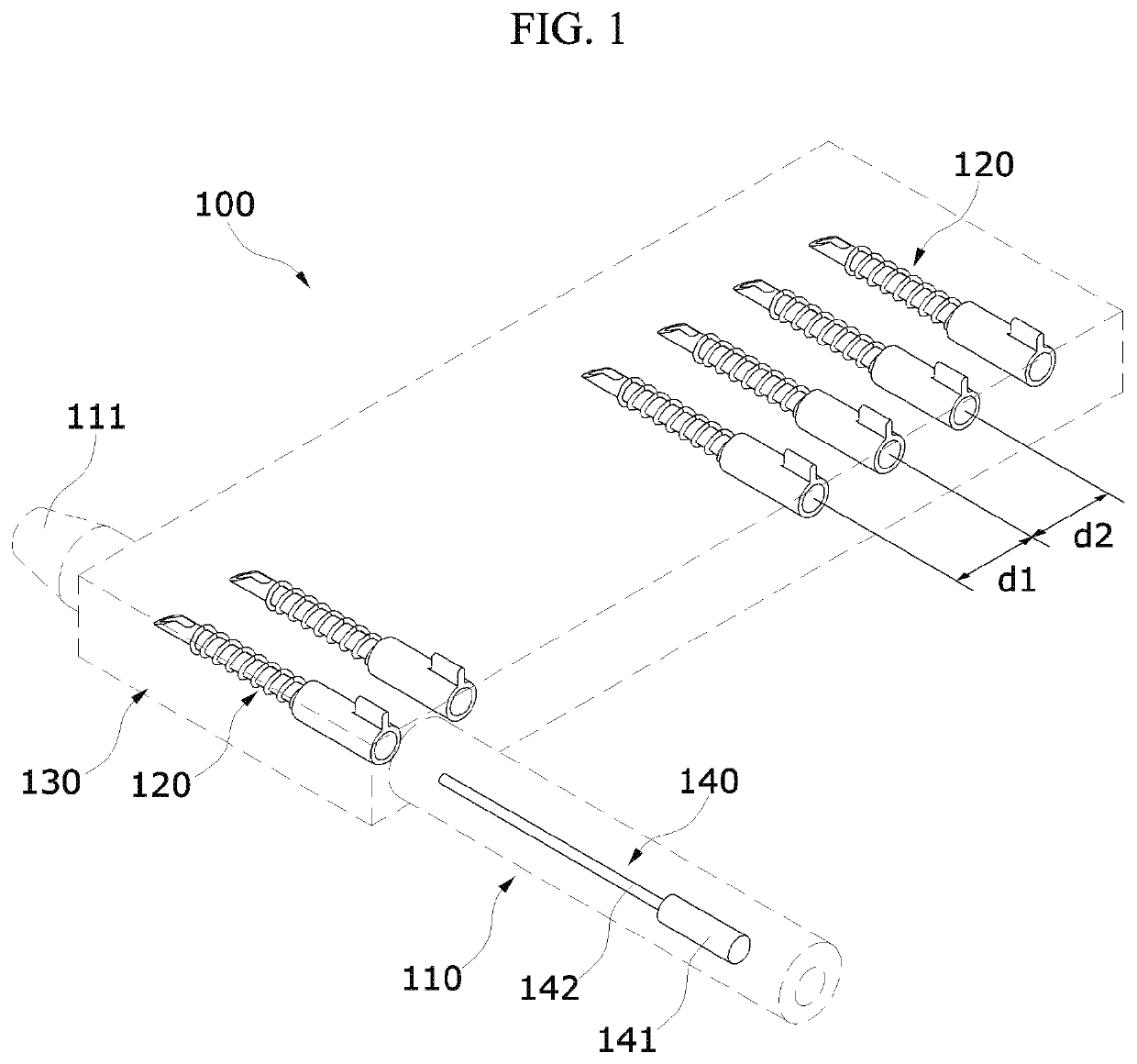
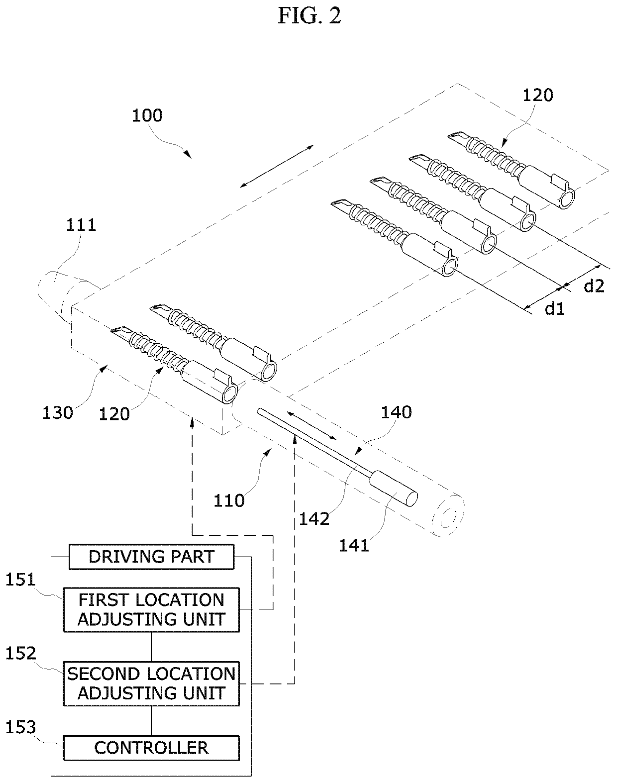
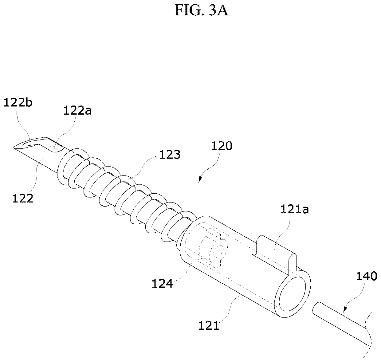
[0051]FIGS. 3A and 3B views illustrating an implant unit of the automatic hair implant apparatus according to the present disclosure.

[0052]Referring to both FIGS. 3A and 3B, the implant unit 120 includes a housing 121, a needle 122, and a buffering member 123.

[0053]The housing 121 forms a body of the implant unit 120.

[0054]The needle 122 is a hollow needle, and protrudes in a longitudinal direction of the housing 121. In this case, the needle 122 has a slit 122a in which a follicle 10 is embedded.

[0055]The slit 122a is formed through a longitudinal direction of the needle 122. The needle 122 includes an exit path 122b which is open in one direction and formed in an inclined shape at one end portion thereof.

[0056]In this case, the housing 121 includes a direction protrusion 121a formed to protrude toward an outer side to have a direction the same as that of the exit path 122b.

[0057]The direction protrusion 121a is a structure configured to determine a direction of the slit 122a of t...

second embodiment

[0071]FIG. 6 is a view illustrating an operation structure of the automatic hair implant apparatus according to the present disclosure.

[0072]Referring to FIG. 6, the cartridge 130 has a cylindrical rotating structure. In this case, in a side surface of the cartridge 130, forward grooves 131 are provided in a horizontal direction, and diagonal grooves 132 are provided in a vertical direction.

[0073]In this case, the diagonal groove 132 has a predetermined step with the forward groove 131. That is, the diagonal groove 132 is formed to have a height smaller than that of the forward groove 131. That is, the implant unit (120 in FIG. 5) may be sequentially moved by one space at a time by rotating the cartridge 130 by one space at a time. Accordingly, the implant unit (120 in FIG. 5) and the push rod (140 in FIG. 5) may be collinearly disposed.

[0074]In a rotating method of the cartridge 130, since a separate moving shaft (not shown) provided in the first location adjusting unit (151 in FIG...


PUM


Abstract

An automatic hair implant apparatus according to the present disclosure includes a cylinder including a nozzle at an exit side and having a supporting part partially opened on a path, an implant unit configured to pass through the nozzle to implant an embedded follicle into target skin, a cartridge disposed on the supporting part of the cylinder and configured to sequentially replace the implant unit, and a push rod configured to guide the implant unit to the nozzle and return to its original position when the follicle is implanted into the target skin.

Description

CROSS-REFERENCE TO RELATED APPLICATION[0001]This application claims priority to and the benefit of Korean Patent Application Nos. 10-2018-0142520 and 10-2019-0026004, filed on Nov. 19, 2018 and Mar. 6, 2019, the disclosure of which is incorporated herein by reference in its entirety.BACKGROUND1. Field of the Invention[0002]The present disclosure relates to an automatic hair implant apparatus, and more specifically, to an automatic hair implant apparatus capable of continuously implanting a follicle by automatically replacing an implant unit, in which the follicle is embedded, during a hair implant procedure.2. Discussion of Related Art[0003]Generally, a procedure of wearing a wig or implanting hair in a hair loss portion for cosmetic purposes to conceal the hair loss portion is increasing.[0004]A manual follicle implanting device is used in the procedure process. The manual follicle implanting device inserts a needle in which a follicle is accommodated into the skin and then presses...

Claims


Application Information

Patent Timeline
Patent Type & Authority Applications(United States)
IPC IPC(8): A61F2/10A61F2/00
CPCA61F2/10A61F2/0095A61B17/3468A61B2017/00752
Inventor BAE, TAE WUKKIM, KYU HYUNGSUH, JUNG WOOKCHOI, EUN CHANGHONG, CHANG HYUK
Owner ELECTRONICS & TELECOMM RES INST
Why Eureka
Try Eureka