Storage cabinet

Inactive Publication Date: 2020-05-21
JIANGSU FINE STORAGE INFORMATION TECH CO L TD
View PDF17 Cites 0 Cited by
  • Summary
  • Abstract
  • Description
  • Claims
  • Application Information

AI Technical Summary

Benefits of technology

[0015]Preferably, an RFID reader is disposed on the back side of the cabinet body and is provided with tags attached to the carriers of the storage units on all the layers and a reader disposed at a position, corresponding to the tags, of a back door of the cabinet body. Articles in the storage units have different information data and respective serial numbers, the storage conditions, such as the remaining storage spaces and the types/serial numbers of articles, of the storage units can be checked by scanning and reading the tags of the storage units by the RFID reader so as to generate category information, then the basic storage condition of the storage cabinet is obtained, and data are transmitted to a main control system to be efficiently and intelligently managed in a unified m

Problems solved by technology

It is hard to store and manage articles and particularly to store and manage a large batch of articles because convenient operation and efficient running can be ensured only if these articles can be conveniently stored, found and taken when used and can be classified without being confused or disordered.
For instance, when a large batch of CDs storing various types of data and information ar

Method used


Image

  • Storage cabinet
  • Storage cabinet

Examples


Example

Embodiment 1

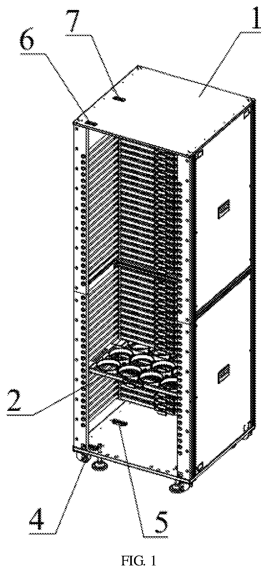
[0022]As shown in FIGS. 1-2, a storage cabinet comprises a cabinet body 1. At least one layer of storage unit 2 is disposed in the cabinet body 1 and is provided with sliding mechanisms 201 capable of being pushed or pulled to move the storage unit 2 forwards or backwards with respect to the cabinet body 1. The storage units 2 are installed layer by layer. In this embodiment, 44 layers of storage units are disposed in the cabinet body 1.

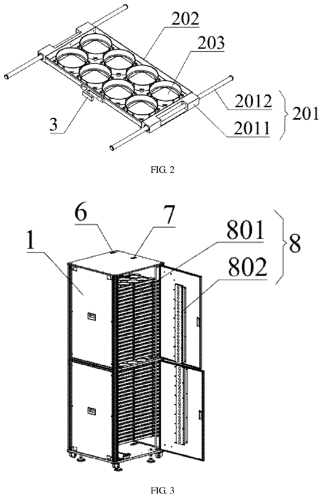
[0023]Each storage unit 2 comprises a carrier 202 provided with at least one tray 203 used for storing articles. The sliding mechanisms 201 are disposed on left sides and the right sides of the carrier 202.

[0024]Each sliding mechanism 201 comprises a sliding rail 2011 disposed on the corresponding carrier and a sliding rod 2012 sleeved with the sliding rail 2011 and having two ends fixed to the cabinet body 1. Obviously, the sliding mechanisms can be replaced with similar mechanisms, such as clamping groove sliding structures, capable of ...

Example

Embodiment 2

[0030]As shown in FIGS. 1-2, on the basis of embodiment 1, a first detection sensor 4 and a second detection sensor 5 are disposed on one side of the inner bottom surface of the cabinet body 1. The first detection sensor 4 is used for detecting the stretching state of the storage units 2. The second detection sensor 5 is used for detecting the restoring state of the storage units 2.

[0031]A first reflector 6 and a second reflector 7 corresponding to the first detection sensor 4 and the second detection sensor 5 in position are disposed on the inner top surface of the cabinet body 1.

[0032]The first detection sensor and the second detection sensor are range finder sensors in the prior art, the first reflector and the second reflector are used for reflecting laser signals back and are also products in the prior art, and the detailed structure of the detection sensors and the reflectors will no longer be described herein.

[0033]Wherein, the mounting positions of the first dete...

Example

Embodiment 3

[0038]As shown in FIG. 3, on the basis of embodiment 1, a RFID reader 8 is disposed on the back side of the cabinet body 1 and is provided with tags 801 attached to the carriers 203 of the storage units 2 on all the layers and a reader 802 disposed at a position, corresponding to the tags 801, of a back door of the cabinet body 1. Articles stored in the storage units have different information data and respective serial numbers. The storage conditions, such as the remaining storage spaces and the types / numbers of articles, of the storage units can be checked by scanning and reading the tags attached to the storage units by the RFID reader so as to generate category information, then the basic storage condition of the storage cabinet is obtained, and data are transmitted to the main control system to be efficiently and intelligently managed in a unified manner and can be checked conveniently.

[0039]Under the enlightenment of the above ideal embodiments of the invention, va...


PUM


Abstract

A storage cabinet includes a cabinet body and is characterized in that at least one layer of storage unit is disposed in the cabinet body and is provided with sliding mechanisms capable of being pushed or pulled to move the storage unit forwards or backwards with respect to the cabinet body, and the storage units are installed layer by layer. The storage units and storage cabinet facilitate storage, taking and classification of a large batch of articles, reduce management cost and have a high degree of intelligence, thus, improving work efficiency.

Description

BACKGROUND OF THE INVENTIONField[0001]The invention relates to a storage device, in particular to a storage cabinet.Background[0002]It is hard to store and manage articles and particularly to store and manage a large batch of articles because convenient operation and efficient running can be ensured only if these articles can be conveniently stored, found and taken when used and can be classified without being confused or disordered. For instance, when a large batch of CDs storing various types of data and information are stored, the surfaces of the CDs need to keep clean; however, the CDs are likely to be stained and damaged and get lost purely through manual management, it is inconvenient to find out required CDs or to take the required CDs for use due to the fact that these CDs are prone to being confused, and consequentially, the efficiency is low, and the requirements in the big data era cannot be met.SUMMARY[0003]To solve the technical problems mentioned above, the invention p...

Claims


Application Information

Patent Timeline
IPC IPC(8): G11B33/04A47B81/06G06K19/07
CPCA47B81/068G11B33/0461G06K19/0723
Inventor LIU, YILINLUO, HUI
Owner JIANGSU FINE STORAGE INFORMATION TECH CO L TD
Why Eureka
Try Eureka