Method for Manufacturing Secondary Battery, Method for Manufacturing Pouch for Secondary Battery, and Pouch for Secondary Battery

a secondary battery and pouch technology, applied in the direction of final product manufacturing, sustainable manufacturing/processing, cell components, etc., can solve the problems of inability to manufacture pouches indefinitely, the depth of the cup formed in the pouches cannot be increased indefinitely, and the volume of the internal space of the case in which the electrode assembly is accommodated does not increase indefinitely, so as to achieve the effect of increasing capacity and weakening the durability of the pouch

Active Publication Date: 2020-05-28
LG ENERGY SOLUTION LTD
View PDF0 Cites 1 Cited by
  • Summary
  • Abstract
  • Description
  • Claims
  • Application Information

AI Technical Summary

Benefits of technology

[0024]According to the present invention, the problem of weakening the durability of the pouch, which may occur in the process of forming the cups having different depths in the pouch may be solved.
[0025]In addition, according to the present invention, the pouch type secondary battery may increase in capacity in comparison to the pouch type secondary battery according to the related art.

Problems solved by technology

However, it is a reality that the volume of the internal space of the case in which the electrode assembly is accommodated does not indefinitely increase due to various constraints.
Particularly, in the case of the pouch type secondary battery, there is a problem that a depth of the cup formed in the pouch does not increase indefinitely.
That is, when each of the cups formed in the pouch has a depth greater than a predetermined depth, minute cracks or the like occur in the pouch, and thus, the pouch is easily broken, and a vulnerable area such as an area on which a whitening phenomenon, in which the pouch is whitened around the cracks, occurs is generated.
This acts as a limiting condition in increasing of the capacity of the pouch type secondary battery.

Method used


Image

  • Method for Manufacturing Secondary Battery, Method for Manufacturing Pouch for Secondary Battery, and Pouch for Secondary Battery
  • Method for Manufacturing Secondary Battery, Method for Manufacturing Pouch for Secondary Battery, and Pouch for Secondary Battery
  • Method for Manufacturing Secondary Battery, Method for Manufacturing Pouch for Secondary Battery, and Pouch for Secondary Battery

Examples


embodiment 1

[0066]A laminate sheet having a thickness 150 μm was pressed to form a first cup and a second cup, thereby manufacturing a pouch. The laminate sheet used a laminate sheet in which a nylon layer having a thickness of 30 μm, an aluminum layer having a thickness of 40 μm, and a PP layer having a thickness of 80 μm are sequentially laminated upward.

[0067]Each of the first cup and the second cup was formed by pressing the laminate sheet by using a mold. In Embodiment 1, the mold pressed the laminate sheet at a pressure of 0.5 Mpa and a speed of 40 mm / sec.

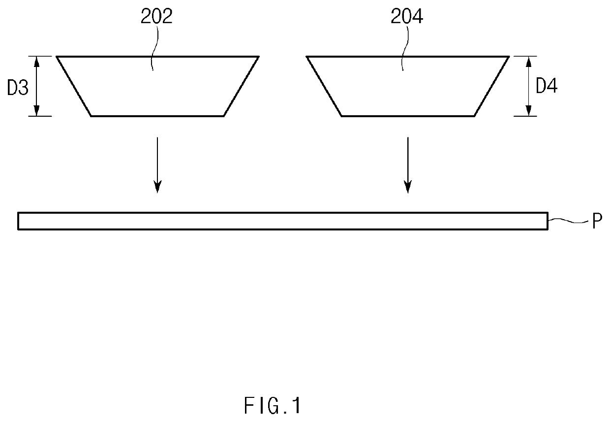
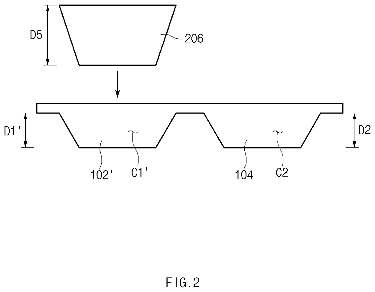
[0068]In a first forming step, the first cup and the second cup were formed until each of a concave portion of the first cup and a concave portion of the second cup has a depth of 1.0 mm. Then, in a second forming step, the laminate sheet constituting the first cup was additionally pressed to form nine pouches in which first cups have concave portions respectively having depths of 4.0 mm, 5.0 mm, 6.0 mm, 7.0 mm, 8.0 mm, 9.0 mm, 10.0 mm, ...

embodiment 2

[0071]A thickness of a laminate sheet, a thickness of each of layers constituting the laminate sheet, and a material of each of the layers constituting the laminate sheet according to Embodiment 2 were the same as those according to Embodiment 1. A pressure and pressing speed of a mold pressing the laminate sheet were also the same as those according to Embodiment 1.

[0072]In a first forming step, a first cup and a second cup were formed until each of a concave portion of the first cup and a concave portion of the second cup has a depth of 2.0 mm. Then, in a second forming step, the laminate sheet constituting the first cup was additionally pressed to form nine pouches in which first cups have concave portions respectively having depths of 4.0 mm, 5.0 mm, 6.0 mm, 7.0 mm, 8.0 mm, 9.0 mm, 9.5 mm, 10.0 mm, and 10.5 mm.

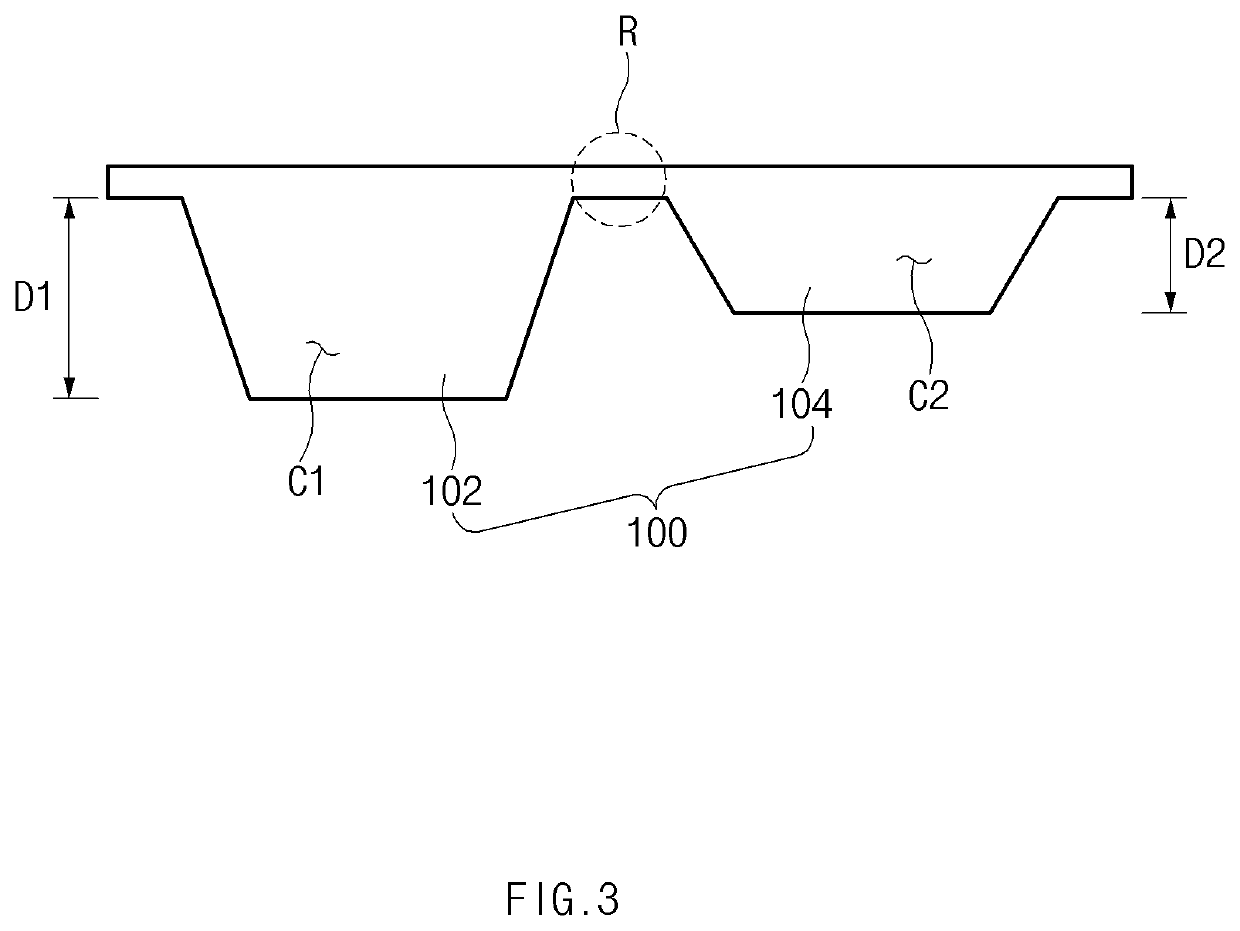
[0073]Here, an inter-area between the first cup and the second cup had a length of 2.0 mm That is, a first curved surface of the inter-area, which is connected to the firs...

embodiment 3

[0075]A thickness of a laminate sheet, a thickness of each of layers constituting the laminate sheet, and a material of each of the layers constituting the laminate sheet according to Embodiment 3 were the same as those according to Embodiment 1. A pressure and pressing speed of a mold pressing the laminate sheet were also the same as those according to Embodiment 1.

[0076]In a first forming step, a first cup and a second cup were formed until each of a concave portion of the first cup and a concave portion of the second cup has a depth of 3.0 mm. Then, in a second forming step, the laminate sheet constituting the first cup was additionally pressed to form eight pouches in which first cups have concave portions respectively having depths of 4.0 mm, 5.0 mm, 6.0 mm, 7.0 mm, 8.0 mm, 8.5 mm, 9.0 mm, and 10.0 mm.

[0077]Here, an inter-area between the first cup and the second cup had a length of 2.0 mm That is, a first curved surface of the inter-area, which is connected to the first cup an...


PUM

PropertyMeasurementUnit
depthaaaaaaaaaa
depthaaaaaaaaaa
depthaaaaaaaaaa

Abstract

Disclosed is a method for manufacturing a secondary battery.
According to the present invention, a problem of weakening durability of a pouch, which may occur in a process of forming cups having different depths in the pouch may be solved.

Description

CROSS-REFERENCE TO RELATED APPLICATIONS[0001]The present application is a national phase entry under 35 U.S.C. § 371 of International Patent Application No. PCT / KR2018 / 015622, filed on Dec. 10, 2018, published in Korean, which claims priority from Korean Patent Application No. 10-2018-0012481, filed on Jan. 31, 2018, the disclosures of which are hereby incorporated by reference in their entireties.TECHNICAL FIELD[0002]The present invention relates to a method for manufacturing a secondary battery and a pouch for the secondary battery, and more particularly, to a method for manufacturing a secondary battery, which is capable of solving a problem of deteriorating durability of a case, which occurs when the case of the secondary battery is formed, and a pouch for the secondary battery.BACKGROUND ART[0003]There are various types of secondary batteries that are repeatedly chargeable and dischargeable. For example, a pouch type secondary battery represents a secondary battery that is manu...

Claims


Application Information

Patent Timeline
Patent Type & Authority Applications(United States)
IPC IPC(8): H01M2/02B29C43/20B29C53/02H01M50/105
CPCB29K2705/02H01M2/0202B29C53/02H01M2/024B29C43/203B29L2031/7146H01M2002/0205Y02E60/10B29C51/08H01M50/105H01M50/131Y02P70/50B29C51/14H01M50/124
Inventor OH, SEI WOONHWANG, SOO JIJUNG, JUNG HWALEE, HO SUBPARK, JIN SEO
Owner LG ENERGY SOLUTION LTD
Why Eureka
Try Eureka