Print system, printing apparatus, method of controlling the printing apparatus, and storage medium that generate print data to be printed using rendered print data

a printing system and printing technology, applied in the field of printing system, can solve the problems of user and it has taken a long time to obtain printed materials

Active Publication Date: 2020-06-04
CANON KK
View PDF0 Cites 1 Cited by
  • Summary
  • Abstract
  • Description
  • Claims
  • Application Information

AI Technical Summary

Benefits of technology

This approach significantly reduces the user wait time for printed materials by allowing preceding processing to be completed in advance, enabling quicker rendering and printing upon user input, even when print settings are changed.

Problems solved by technology

It has, therefore, taken a long time to obtain the printed material.
There is thus a problem in that it has taken a long time for the user to obtain the printed material after inputting the print instruction.

Method used


Image

  • Print system, printing apparatus, method of controlling the printing apparatus, and storage medium that generate print data to be printed using rendered print data
  • Print system, printing apparatus, method of controlling the printing apparatus, and storage medium that generate print data to be printed using rendered print data
  • Print system, printing apparatus, method of controlling the printing apparatus, and storage medium that generate print data to be printed using rendered print data

Examples


first embodiment

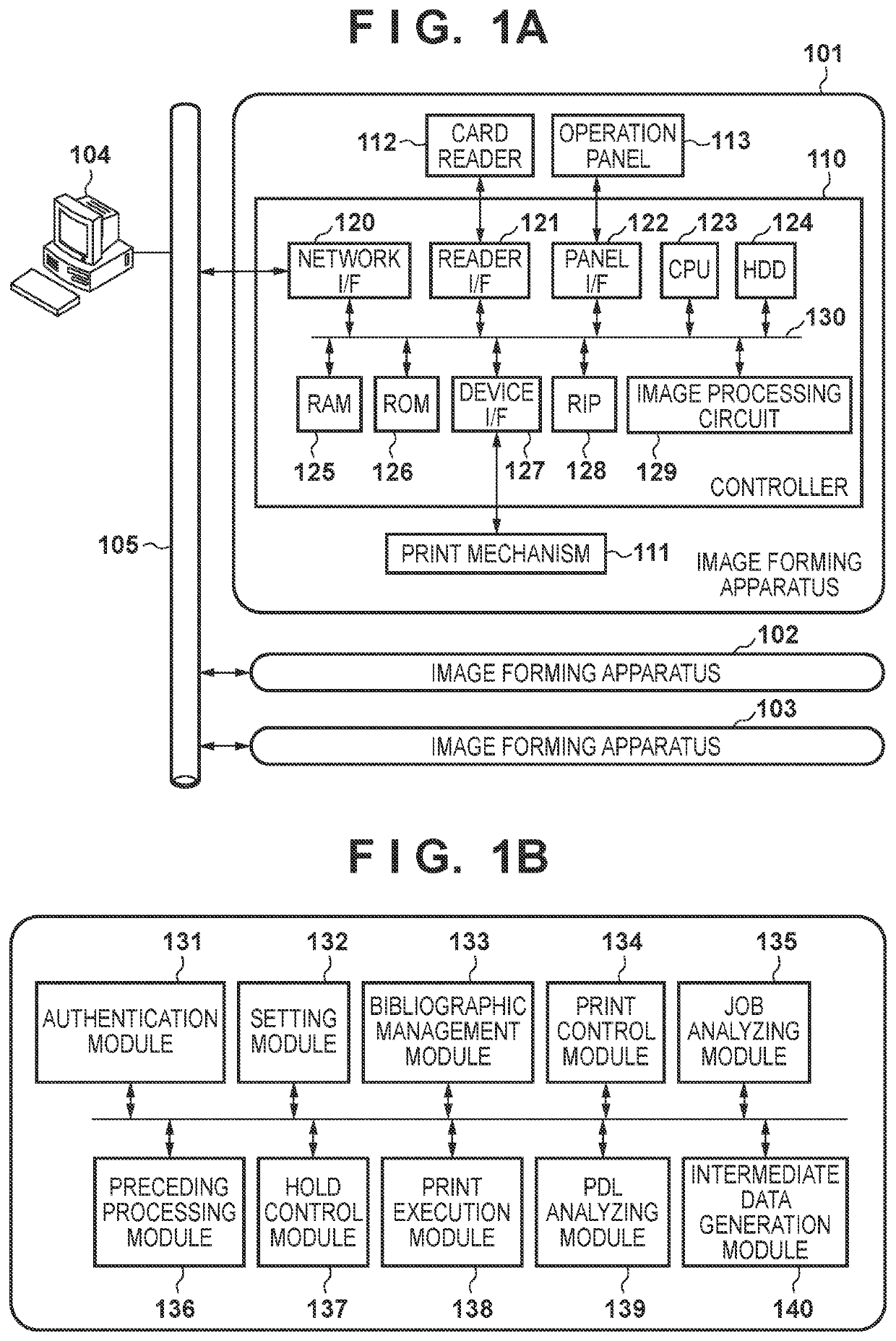
[0035]FIG. 1A is a diagram for describing an example of the configuration of a print system including image forming apparatuses according to a first embodiment of the present invention.

[0036]Image forming apparatuses 101 to 103 may be any one of a multi-function peripheral (MFP), a single-function printer (SFP), or a laser beam printer (LBP). The image forming apparatuses 101 to 103 may be printing apparatuses using printing methods aside from MFP, SFP, or LBP. Although FIG. 1A illustrates an example in which there are three image forming apparatuses, there may be any number of apparatuses greater than or equal to one. The image forming apparatuses 101 to 103 are connected by a local area network (LAN) 105 to a host computer (a personal computer (PC)) 104 that makes various types of instructions. The image forming apparatuses 101 to 103 execute processing in response to printing instructions from the host computer 104. If a plurality of image forming apparatuses are connected by the...

second embodiment

[0101]A second embodiment of the present invention will be described next. Note that the system configuration, the hardware configuration of the image forming apparatuses 101 to 103, and so on according to the second embodiment are the same as those described above in the first embodiment, and thus, descriptions thereof will be omitted.

[0102]The second embodiment describes an example in which the image forming apparatus 101 has a server function, and a user instructs the image forming apparatus 102 (or 103) to print after the image forming apparatus 101 has received the print job from the PC 104. In the following, configurations that are the same as those in the first embodiment will not be described, and the descriptions will focus on the differences from the first embodiment.

[0103]FIG. 11 is a sequence chart for describing an example of a print processing sequence carried out in the print system according to the second embodiment. Note that the processing executed by the image for...

third embodiment

[0127]A third embodiment of the present invention will be described next. Note that the system configuration, the hardware configuration of the image forming apparatuses 101 to 103, and so on, according to the third embodiment are the same as those described above in the first embodiment, and thus, descriptions thereof will be omitted.

[0128]In the above-described first and second embodiments, the original print settings of the print job being processed are obtained in step S403 of FIG. 4, and the preceding processing is carried out on the basis thereof. A desired print job may, however, for example, be selected from the print job list 1701 in FIG. 17, and the print settings of the selected print job may be changed by pressing the print settings button 1703. The selected print job may then be printed. In this case, the print settings are not finalized until the user presses the print start button 1702 to instruct the printing to start. Accordingly, if the preceding processing is carr...


PUM


Abstract

A printing apparatus receives a print job including print data held in a storage, performs processing of rendering of the print data, and generates, after a print instruction for the print job is input, print data to be printed based on the rendered print data. In a case in which print settings for the print job change from first print settings to second print settings, while the print job is held, first rendered print data and second rendered print data are generated based on the print data. The first rendered print data is not used for generating the print data to be printed, and the second rendered print data is used for generating the print data to be printed. In addition, the first rendered print data is generated in accordance with the first print settings, and the second rendered print data is generated in accordance with the second print settings.

Description

[0001]This application claims the benefit of Japanese Patent Application No. 2017-148202, filed Jul. 31, 2017, which is hereby incorporated by reference herein in its entirety.BACKGROUND OF THE INVENTIONField of the Invention[0002]The present invention relates to a print system, a printing apparatus, a method of controlling the printing apparatus, and a storage medium.Description of the Related Art[0003]“Hold printing” has been used for some time, both as a way to prevent situations in which a printed material, printed and discharged from a printing apparatus, or the like, is left alone, and information on the printed material is leaked as a result, and as a way to repeatedly print the same printed material. In hold printing, the printing apparatus does not print a received print job immediately, but rather holds (saves) the print job in the printing apparatus, as disclosed in Japanese Patent Laid-Open No. 2005-242735, for example. Printing is then executed on the basis of the print...

Claims


Application Information

Patent Timeline
Patent Type & AuthorityApplications(United States)
IPC IPC(8): G06F3/12
CPCG06F3/126G06F3/1247H04N1/00209G06F3/1285G06F3/1222G06F3/1269G06F3/1267G06F3/1258G06F3/1238G06F3/1211
InventorYOKOYAMA, HIDEHIKO
OwnerCANON KK