
Terminal fitting and connector provided therewith

a technology of connecting parts and fittings, applied in the direction of coupling contact members, coupling device connections, securing/insulating coupling contact members, etc., can solve the problems of breaking the locking lance, external matter, wires, etc., to prevent the breakage or damage form relatively easily, and avoid complicated structure of the locking lance

Inactive Publication Date: 2020-06-04
SUMITOMO WIRING SYST LTD
View PDF15 Cites 9 Cited by
  • Summary
  • Abstract
  • Description
  • Claims
  • Application Information

AI Technical Summary

Benefits of technology

The patent describes a technical solution to prevent damage to a locking lance during installation of a terminal fitting into a housing. The locking lance can be bent or displaced during installation, which can cause it to break. The patent proposes a solution where a hook is added to the end of the locking lance to restrict its movement and avoid damage. This hook interacts with a hooking portion on the terminal body or on the outer wall of the cavity to prevent the locking lance from moving in the opposite direction. This results in a stronger holding force of the terminal fitting to the housing.

Problems solved by technology

In the above case, external matter, such as a wire, might interfere with and be caught by the housing connecting part before the terminal fitting is accommodated in the housing.
External matter may interfere with the tip of the locking lance before the terminal fitting is accommodated into the housing.
There is concern that such interference may displace the locking lance toward the side opposite to the side toward which the locking lance is deflected in the insertion process into the cavity, and such inverted displacement could break the locking lance.

Method used


Image

  • Terminal fitting and connector provided therewith
  • Terminal fitting and connector provided therewith
  • Terminal fitting and connector provided therewith

Examples


Embodiment Construction

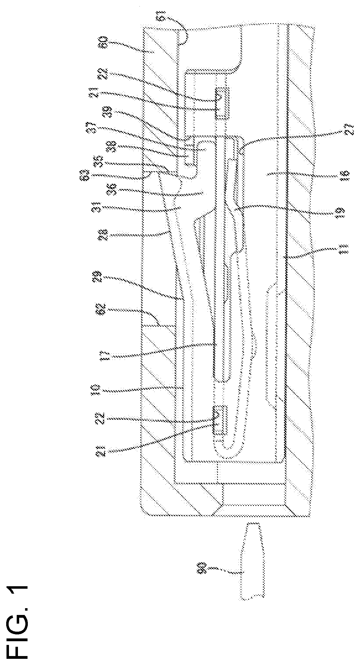
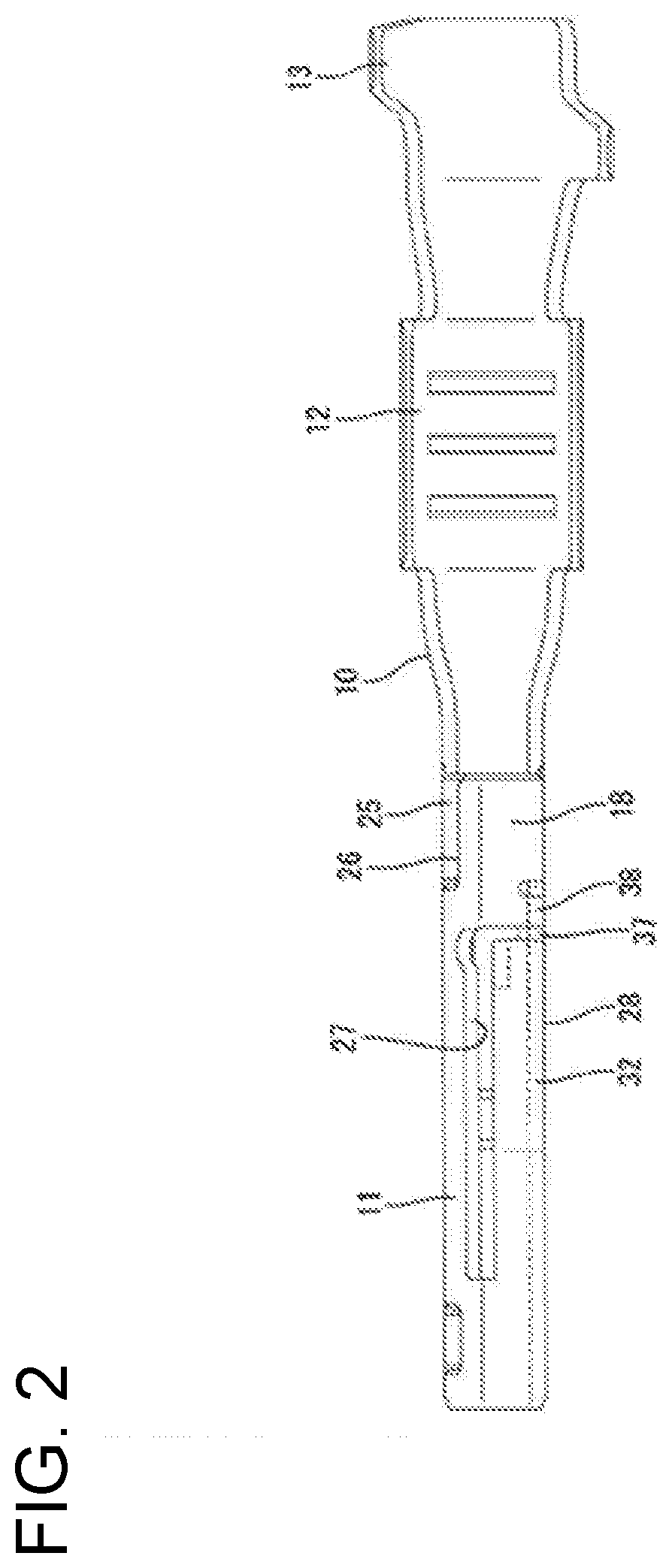
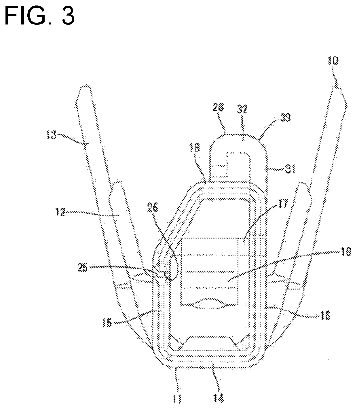
[0025]An embodiment of the invention is described with reference to FIGS. 1 to 7. A terminal fitting 10 according to this embodiment is formed integrally or unitarily by applying bending, folding, embossing or the like to a conductive metal plate is stamped or cut into a development shape shown in FIG. 7. The terminal fitting 10 is to be accommodated into a housing 60 of a connector. Note that, in the following description, a left side of FIGS. 1, 2 and 5 is referred to as a front side concerning a front-rear direction and a vertical direction is based on a vertical direction of FIGS. 1 and 3 to 6.

[0026]The housing 60 is made of synthetic resin and includes, as shown in FIG. 1, at least one cavity 61 penetrating in the front-rear direction and at least one lance receiving portion 62 at least partly intersecting and communicating with the cavity 61. Further, the housing 60 has a locking surface 63 along a direction intersecting with an insertion direction of the terminal fitting 10 i...


PUM


Abstract

A terminal fitting (10) includes a terminal body (11) to be inserted into a cavity (61) of a housing (60), and a deflectable and deformable locking lance (28) obliquely extending from a base end part connected to an outer wall of the terminal body (11) to a tip part, the tip part being retained and locked to a wall surface of the cavity (61). A hook (36) is at the tip of the locking lance (28). A hooking portion (38) capable of contacting the hook (36) from a side opposite to a side toward which the locking lance (28) is deflected in an insertion process into the cavity (61) is connected to the outer wall of the terminal body (11).

Description

BACKGROUNDField of the Invention[0001]The present invention relates to a terminal fitting and to a respective connector.Related Art[0002]Japanese Unexamined Patent Publication No. 2017-168445 discloses a terminal fitting a locking lance. The terminal fitting is locked in a contact chamber of a housing by the locking lance, and a housing connecting part is formed on a tip of the locking lance. FIG. 2 of Japanese Unexamined Patent Publication No. 2017-168445 shows a state where a lock shoulder (reference numeral 149 in FIG. 2) of the housing connecting part is in contact with a wall (reference numeral 320 in FIG. 2) of the housing.[0003]In the above case, external matter, such as a wire, might interfere with and be caught by the housing connecting part before the terminal fitting is accommodated in the housing. Thus, the locking lance might be inclined in an inverting direction and broken.[0004]The invention was completed on the basis of the above situation and aims to provide a termi...

Claims


Application Information

Patent Timeline
IPC IPC(8): H01R13/432H01R13/11
CPCH01R13/11H01R4/185H01R13/432H01R13/42H01R13/502H01R13/111
Inventor ZHOU, TIANYU
Owner SUMITOMO WIRING SYST LTD
Learn More