Snap Trap Sheild

a technology for traps and mice, applied in the field of adapting mouse traps and pest control devices, can solve the problems of mouse being unable to drag the trap away, unable to suffer a slow death, etc., and achieve the effect of effective and humane

Inactive Publication Date: 2020-06-11
SCHURMAN DAVID B
View PDF0 Cites 6 Cited by
  • Summary
  • Abstract
  • Description
  • Claims
  • Application Information

AI Technical Summary

Benefits of technology

[0013]The invention of the present disclosure is intended to be used with the trap to improve its function in killing a mouse humanely and efficiently. It is designed to force the mouse to align its head in such a way that the striking bar of the trap will hit the mouse in the head or neck and kill it instantly to prevent the mouse from suffering. It is also intended to prevent the mouse from seeing the retaining bar of the trap start to move when the trigger mechanism is activated thus keeping the mouse from being startled and jumping back upon seeing this movement and escaping the trap. It will also generally cause the mouse to force its mouth into a confined space between the trigger mechanism holding the bait and the top of an inner housing in order to reach the bait thus causing the trigger mechanism to be activated more reliably. Further, the present disclosure covers the trap so that children and pets cannot accidently trigger the trap.
[0014]The present disclosure, an improvement to the snap trap mouse trap consists of two parts in addition to the trap itself, an outer housing and an inner housing. The outer housing fits over the trap completely enclosing it except for an access opening in the front adjacent to the trigger mechanism of the trap so the mouse can only access the trap through this opening. The inner housing is locked into the outer housing thus positioning it precisely over the trigger mechanism of the trap. The inner housing prevents the mouse from going too far onto the trap. The inner housing also blocks the mouse from seeing the movement of the trap when it is sprung. The inner housing also forces the mouse to push it nose into a confined space to get the bait thus triggering the trap more efficiently.

Problems solved by technology

A major problem with the trap that it allows the mouse to approach the bait from any direction letting the striking bar hit and trap the mouse by any part of its body causing the mouse to possibly suffer a slow death or even be able to drag the trap away.
It is a further problem with the trap that often the trigger mechanism is not activated by the mouse sometimes allowing the mouse to eat all the bait without triggering the trap.
Possibly the most troubling problem with the standard snap trap is that that the trap mechanism is exposed so that pets and children (or even a careless adult) can activate the trap thus causing injury.

Method used


Image

  • Snap Trap Sheild
  • Snap Trap Sheild
  • Snap Trap Sheild

Examples


Embodiment Construction

[0031]Referring now the drawings with more specificity, the present invention essentially provides a mousetrap and improved mousetrap cover. The preferred embodiments of the present invention will now be described with reference to FIGS. 1-7 of the drawings. Variations and embodiments contained herein will become apparent in light of the following descriptions.

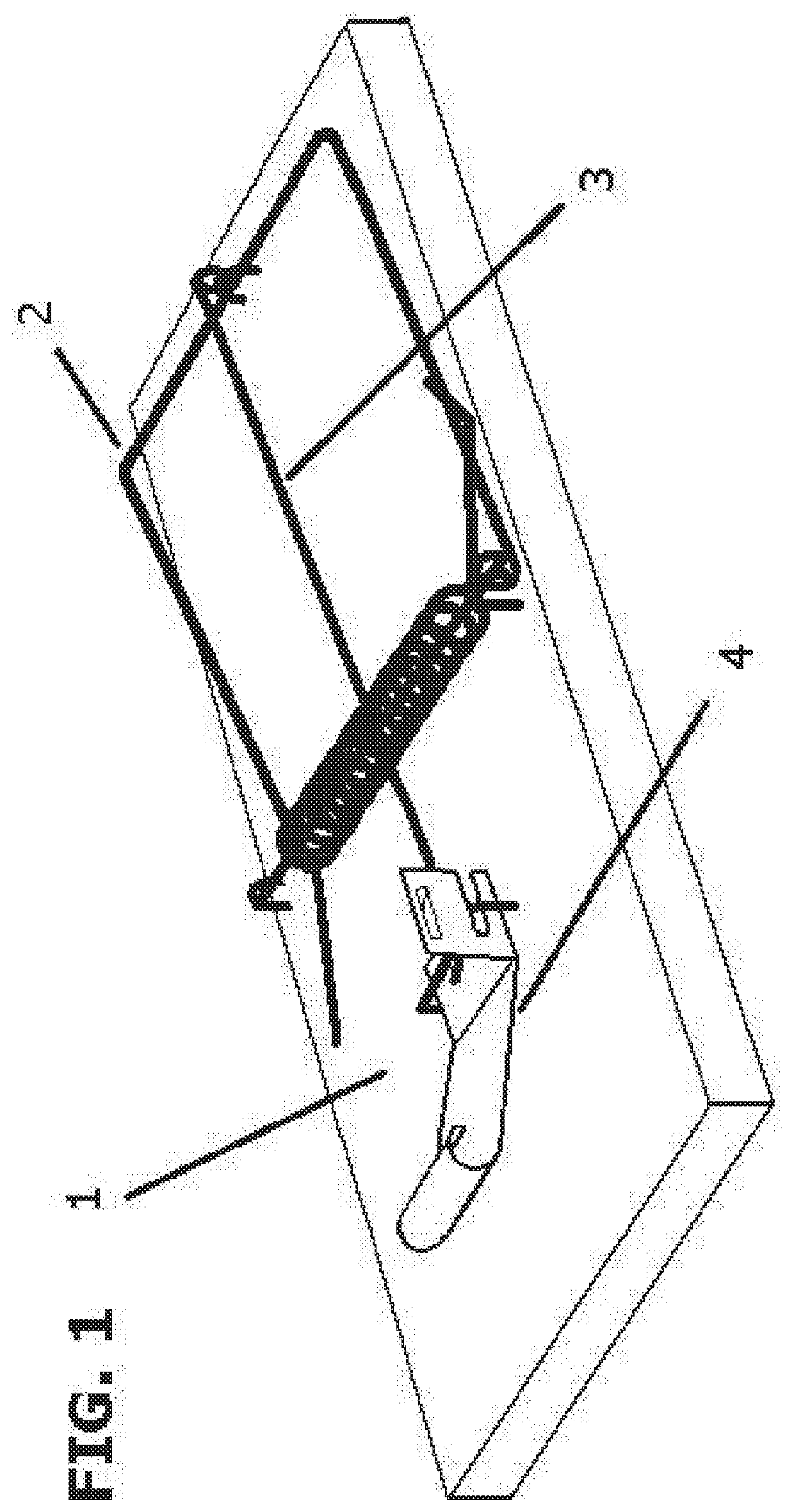
[0032]Looking to FIG. 1 a mousetrap 1 is shown. A mousetrap 1 is composed of a striking bar 2, retaining bar 3, trigger mechanism 4 and can optionally be outfitted with bait 15. Operation of mousetrap 1 is similar to conventional snap traps and such snap traps can be used with the invention of the present disclosure.

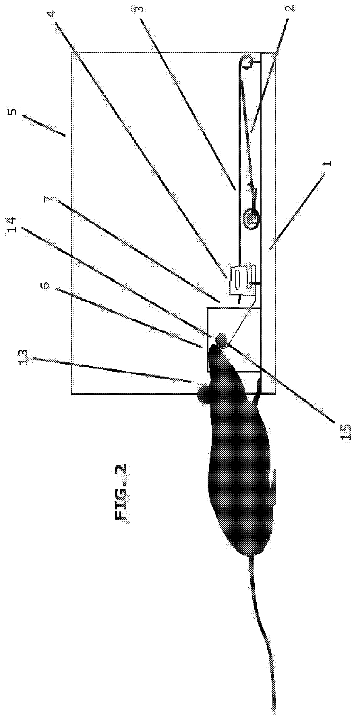
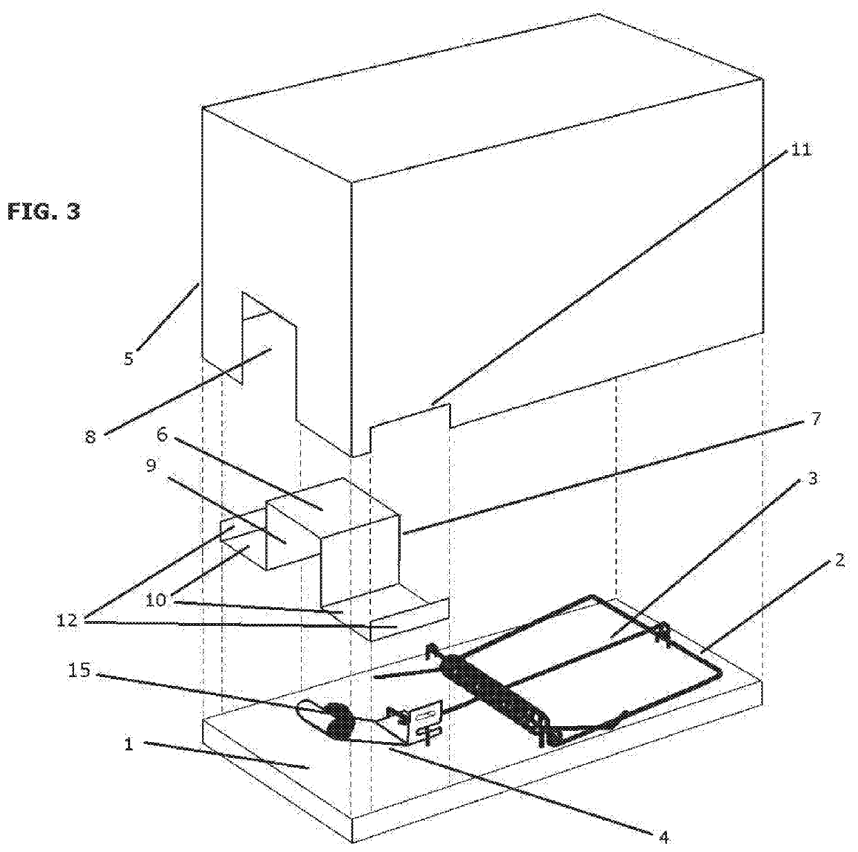
[0033]FIG. 2 shows the present disclosure. A trap 1 cover consists of an outer housing 5 and an inner housing 6 in conjunction with the trap 1 (see FIG. 3 and FIG. 4). A purpose of the outer housing 5 is to cover the trap 1 so the mouse (as shown) can only enter the housing through access opening 8, in such a way t...


PUM


Abstract

An improved, humane mousetrap apparatus is contemplated. The mousetrap apparatus having a trap, the trap having a base, a striking bar, a retaining bar, and a trigger, an inner housing having an access opening, positioning tabs, and securing tabs and an outer housing having an access opening, a pocket, and at least four walls, the apparatus retaining a mouse in a position for the striking bar to strike the rodent in the head or neck.

Description

[0001]This application is a national stage application of PCT / US17 / 34724 with international filing date 26 May 2017 which claimed the benefit of provisional application No. 62 / 392,323 filed 27 May 2016.FIELD OF THE INVENTION[0002]The present invention generally relates to an adaptation mouse traps and pest control devices.BACKGROUND[0003]There is currently no humane and effective way to get mice (rats, etc) out of a building. Thus, there is a need for changing the methods that are safe and effective for rodent removal.[0004]The present disclosure pertains to traditional wooden framed snap traps which. As the trap is available in sizes for mice and rats, any reference to mice can also be taken to apply to rats or other rodents. The principles put forth in this writing can also apply to other styles of snap traps however the traditional wooden frame snap trap is illustrative for the purposes of explaining the working mechanisms and operation of this invention.[0005]While there are oth...

Claims


Application Information

Patent Timeline
Patent Type & Authority Applications(United States)
IPC IPC(8): A01M23/30A01M23/16
CPCA01M23/245A01M23/16A01M23/30A01M23/08A01M25/004A01M31/002
Inventor SCHURMAN, DAVID B
Owner SCHURMAN DAVID B
Why Eureka
Try Eureka