
Method for calculating earth pressure load on a tunnel

a tunnel and earth pressure load technology, applied in the field of tunnel theory and underground engineering foundation, can solve the problems of reducing the quality of tunnel service, posing a certain threat to operational safety, complex modeling, and difficult to determine parameters, and achieve the effect of accurately reflecting earth pressure load

Active Publication Date: 2020-06-11
SUZHOU UNIV
View PDF0 Cites 18 Cited by
  • Summary
  • Abstract
  • Description
  • Claims
  • Application Information

AI Technical Summary

Benefits of technology

The purpose of this patent text is to provide a method for calculating the pressure load on a tunnel to detect any deformation in time and analyze the performance of the tunnel structure. The present invention simplifies the calculation of the load and takes into account the complex and varied external environment, making it more accurate compared to traditional methods. It also employs a tunnel physical model and deformation data to accurately reflect the pressure load on the tunnel.

Problems solved by technology

After years of operation, the tunnels built in the early years have problems such as longitudinal uneven settlement, lateral deformation and long-term leakage, which reduces the quality of tunnel service and poses a certain threat to operational safety.
This theoretical concept is in accordance with the mechanical principle of underground engineering, but there are problems of complex modeling.
Theoretically, it can adapt to the complex and variable geological environment, but it is necessary to assume the load mode to reflect the soil action, so it is not possible to reflect changes in the soil environment, and there is a problem that the parameters are difficult to determine.
However, the durability and reliability of the sensors are seriously affected by the harsh underground environment, and the measured data are highly discrete.
In summary, the existing methods are not suitable for the complex and varied external environment, and the determination of the earth pressure load of the tunnel during operation is a new problem.

Method used


Image

  • Method for calculating earth pressure load on a tunnel
  • Method for calculating earth pressure load on a tunnel
  • Method for calculating earth pressure load on a tunnel

Examples


embodiment

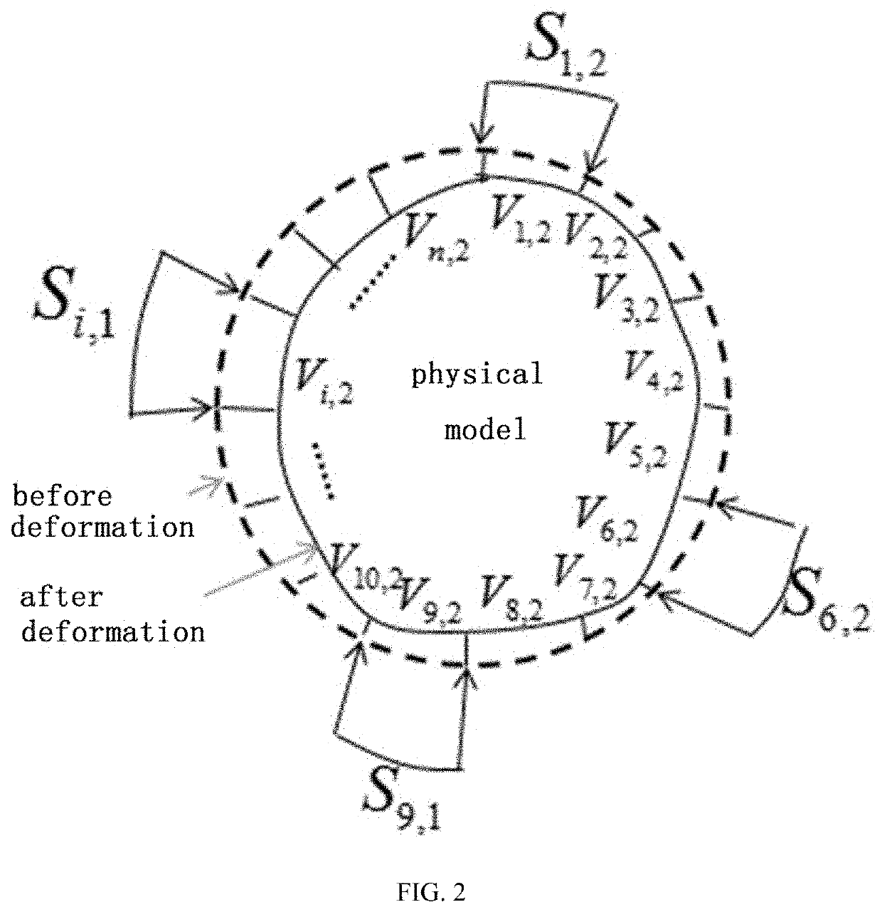
[0032]A method for calculating earth pressure load on a tunnel, comprising the following steps:

[0033](1) Expressing the relationship between the earth pressure load and the structural deformation of tunnel under real working conditions.

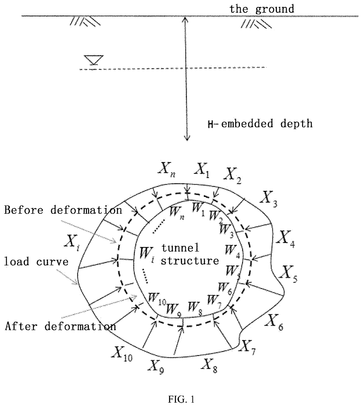
[0034]As shown in FIG. 1, the earth load, including foundation resistance and earth pressure, is regarded as the full space structural load outside the tunnel. All loads are differentiated into n unknown forces {Xi}, resulting in corresponding full-space shift {Wi}, where i is the position of the tunnel location i, that is, {Xi} is the load at position i and {Wi} is the shift at position i. The full-space loads under real working conditions are expressed by [X]n*1, and the full-space deformation under real working conditions is expressed by [W]n*1.

[0035](2) Expressing the relationship between earth pressure load and structural deformation under design conditions.

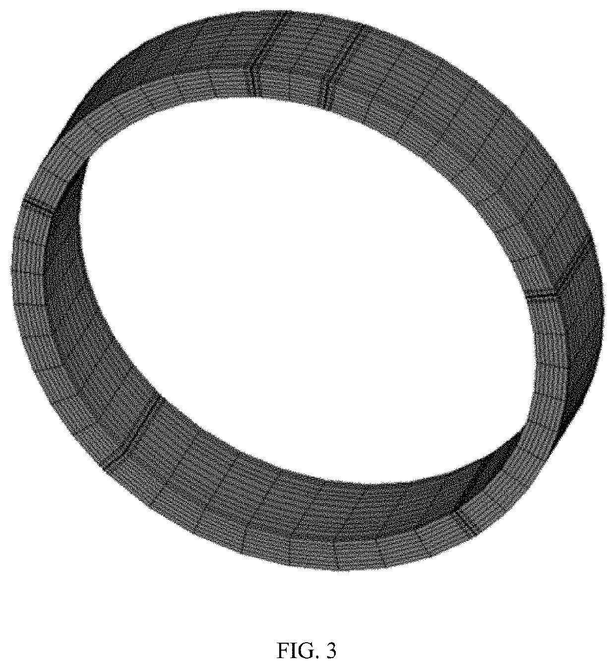
[0036]A three-dimensional finite element model of tunnel structure (shown in FIG. 3) is es...


PUM


Abstract

A method for calculating an earth pressure load on a tunnel includes the following steps: (1) taking interaction between external soil and a tunnel structure in an actual operation condition as an earth pressure load acting on the tunnel structure; (2) establishing a physical model for the tunnel structure; (3) designing, on the basis of the physical model for the tunnel structure, a plurality of structural loads in different operation conditions to obtain a plurality of different structural deformations; and (4) drawing an inference according Betti's theorem, and establishing a physical model for an original structure, such that a load on the original structure, namely an earth pressure load on the tunnel, can be directly calculated according to a load-deformation relationship of the physical model and deformation of the original structure. The above method can determine distribution and size of an actual earth pressure load on a tunnel.

Description

FIELD OF THE INVENTION[0001]The present invention relates to the theory of a tunnel and an underground engineering foundation, and particularly relates to a calculation method for earth pressure load of a tunnel during operation period.BACKGROUND OF THE INVENTION[0002]After years of operation, the tunnels built in the early years have problems such as longitudinal uneven settlement, lateral deformation and long-term leakage, which reduces the quality of tunnel service and poses a certain threat to operational safety. During the operation period, effective evaluation of structural performance and reasonable measures to control tunnel diseases are important guarantees for ensuring rail transit safety. The earth pressure load is the boundary condition for the calculation of tunnel structure performance.[0003]In the prior arts, the continuum theory regards the complex soil action and the tunnel structure as a unified mechanical system, and the stress of contact surface between different...

Claims


Application Information

Patent Timeline
IPC IPC(8): G01L5/00G01S17/89G01B11/16G06F30/23
CPCG06F30/23G01S17/89G01L5/00G01B11/167E21F17/18G06F17/13E21D11/00G01S17/42G01S17/88G06F30/13G06F2111/10
Inventor LI, PAN
Owner SUZHOU UNIV
Learn More