Lidar-based Trailer Tracking

a trailer tracking and trailer technology, applied in the direction of process and machine control, using reradiation, instruments, etc., can solve the problems of insufficient accuracy of techniques to the extent necessary to operate in an autonomous mode, and the effect of affecting techniques

Active Publication Date: 2020-06-11
WAYMO LLC
View PDF0 Cites 18 Cited by
  • Summary
  • Abstract
  • Description
  • Claims
  • Application Information

AI Technical Summary

Benefits of technology

[0008]In a further example, the vehicle is a tractor-trailer. In this case, the driving unit is a tractor unit, and the articulating unit is a trailer. The trailer has a kingpin pivotally connected to a fifth-wheel of the tractor unit. The one or more sensors may include a Lidar sensor disposed on a roof of the tractor unit. In this case, the sensor data may be Lidar point cloud data.
[0009]And in yet another example, the control system may be further configured to set a driving operation according to the determined pose of the articulating unit.
[0010]According to other aspects of the technology, a method of operating a vehicle in an autonomous driving mode is provided. The method comprises receiving sensor data obtained by one or more sensors of a perception system of the vehicle; estimating, by one or more processors of the vehicle, an orientation of an articulating unit coupled to a driving unit of the vehicle based on the obtained sensor data; determining, by the one or more processors, a pose of the articulating unit according to the estimated orientation; and setting a driving operation in the autonomous driving mode according to the determined pose of the articulating unit.
[0011]The method may further comprise smoothing, by the one or more processors, the estimated orientation of the artic...

Problems solved by technology

However, such techniques may not be sufficiently accurate to the extent necessary to operate in an autonomous mode.
The techniques can also be ...

Method used


Image

  • Lidar-based Trailer Tracking
  • Lidar-based Trailer Tracking
  • Lidar-based Trailer Tracking

Examples


example implementations

[0047]In view of the structures and configurations described above and illustrated in the figures, various implementations will now be described.

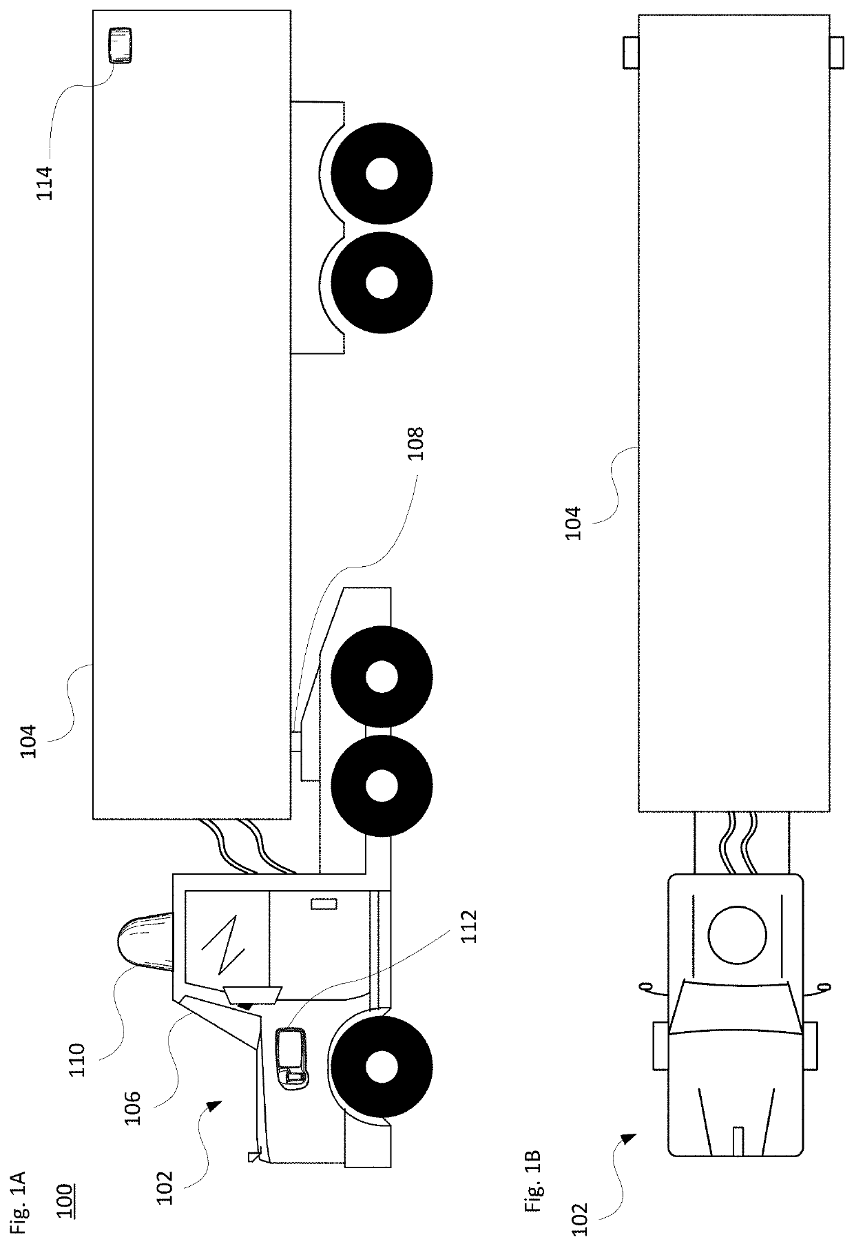
[0048]Information obtained from one or more sensors is employed so that the vehicle may operate in an autonomous mode. Each sensor, or type of sensor, may have a different range, resolution and / or field of view (FOV).

[0049]For instance, the sensors may include a long range, narrow FOV Lidar and a short range, tall FOV Lidar. In one example, the long range Lidar may have a range exceeding 50-250 meters, while the short range Lidar has a range no greater than 1-50 meters. Alternatively, the short range Lidar may generally cover up to 10-15 meters from the vehicle while the long range Lidar may cover a range exceeding 100 meters. In another example, the long range is between 10-200 meters, while the short range has a range of 0-20 meters. In a further example, the long range exceeds 80 meters while the short range is below 50 meters. Intermedi...


PUM


Abstract

The technology relates to autonomous vehicles having articulating sections such as the trailer of a tractor-trailer. Aspects include approaches for tracking the pose of the trailer, including its orientation relative to the tractor unit. Sensor data is analyzed from one or more onboard sensors to identify and track the pose. The pose information is usable by on-board perception and/or planning systems when driving the vehicle in an autonomous mode. By way of example, on-board sensors such as Lidar sensors are used to detect the real-time pose of the trailer based on Lidar point cloud data. The orientation of the trailer is estimated based on the point cloud data, and the pose is determined according to the orientation and other information about the trailer. Aspects also include determining which side of the trailer the sensor data is coming from. A camera may also detect trailer marking information to supplement the analysis.

Description

BACKGROUND[0001]Autonomous vehicles, such as vehicles that do not require a human driver, can be used to aid in the transport of trailered (e.g., towed) cargo, such as freight, livestock or other items from one location to another. Other types of articulated vehicles may also transport cargo or passengers. Such vehicles may operate in a fully autonomous mode without any in-vehicle passenger input or a partially autonomous mode where a person may provide some driving input. When making turns in these modes, the trailer portion of the vehicle may not be aligned with the tractor portion. It is possible to detect or estimate the positioning of the trailer through various techniques. However, such techniques may not be sufficiently accurate to the extent necessary to operate in an autonomous mode. The techniques can also be adversely affected by sensor signal information that varies depending on the orientation of the trailer relative to the tractor as the vehicle turns.BRIEF SUMMARY[000...

Claims


Application Information

Patent Timeline
IPC IPC(8): G01S17/66G01S17/88G01S17/42G05D1/02B60W10/20B60W10/04B60W30/18
CPCB60W2710/20G01S17/42G05D2201/0213B60W2554/00B60W30/18009G05D1/0238B60W2420/42B60W2300/145G01S17/66B60W2420/52B60W10/20B60W2400/00B60W2720/106B60W10/04G01S17/88B60W40/10B60W2050/0052B60W2520/22B60W2300/10B60W2300/12G01S17/86G01S17/87G01S17/931G01S17/89
Inventor CHEN, MINGCHENGLAUTERBACH, CHRISTIANPITZER, BENJAMINMORTON, PETER
Owner WAYMO LLC
Why Eureka
Try Eureka