Image forming apparatus

Inactive Publication Date: 2020-06-11
KONICA MINOLTA INC
View PDF4 Cites 4 Cited by
  • Summary
  • Abstract
  • Description
  • Claims
  • Application Information

AI Technical Summary

Benefits of technology

[0012]The present invention, which has been made in consideration of such a technical background as described above, is capable of, without requiring a more complicated configuration in a fusi

Problems solved by technology

In a fusing device such as described above, paper jams and image noise can be caused in a nip region formed by the pad member and the pressure member e.g. pressure roller, depending on the contact condition between the members.
Most fusing devices, however, are hardly capable of controlling the contact condition between the members because of their complicated pressure welding configurations.
In Japanese Unexamined Patent Application Publication No. 2014-032342, the image forming apparatus simply relocates the pressure member away from the fusing member, which means the image forming apparatus is not capable of optimizing the distribution of interfacial pressure in the nip region precisely with reference

Method used


Image

  • Image forming apparatus
  • Image forming apparatus
  • Image forming apparatus

Examples


Embodiment Construction

[0026]Hereinafter, one or more embodiments of the present invention will be described with reference to the drawings. However, the scope of the invention is not limited to the disclosed embodiments.

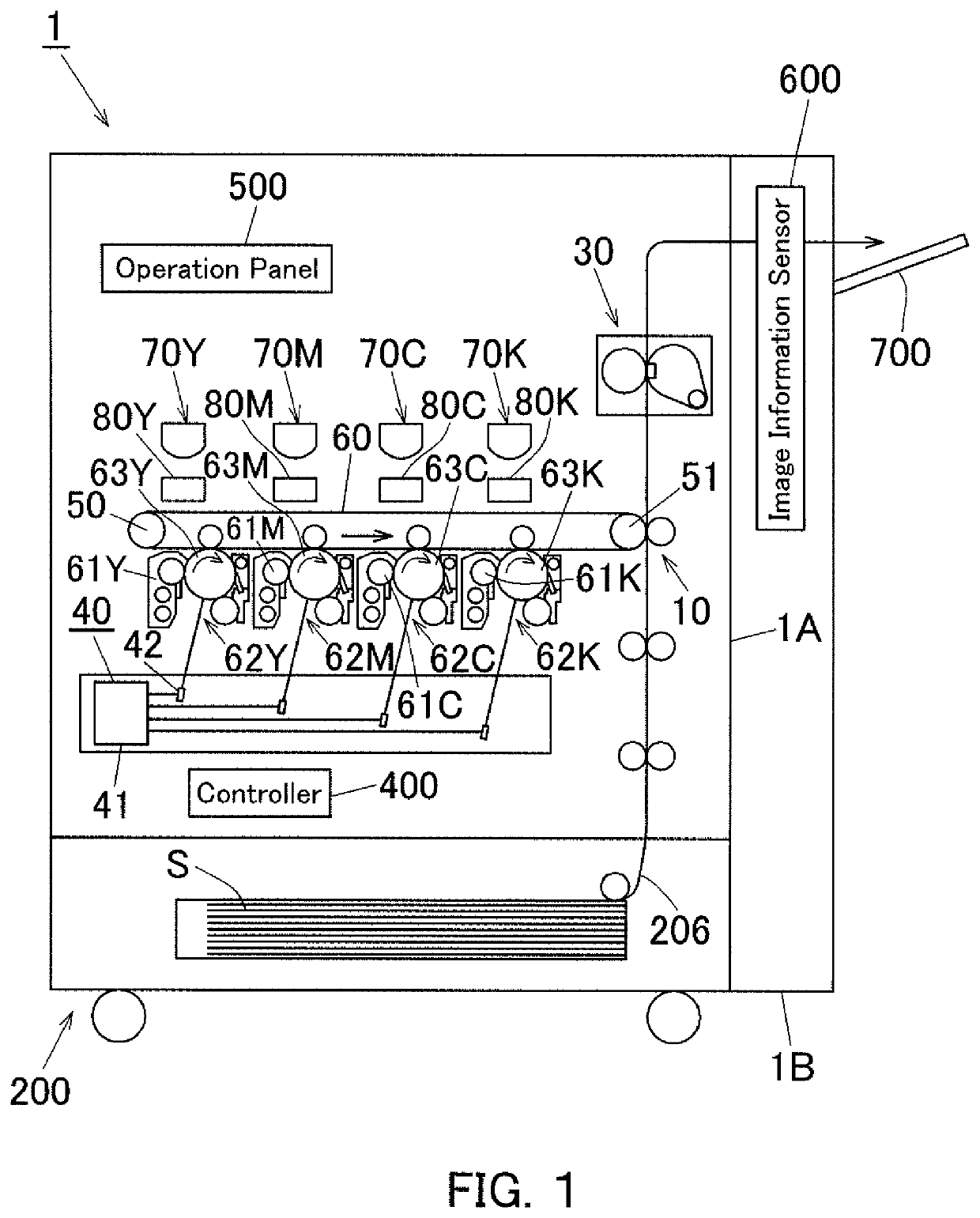
[0027]FIG. 1 is a schematic diagram illustrating a configuration of an image forming apparatus 1 according to one embodiment of the present invention. In this embodiment, a tandem color printer is employed as the image forming apparatus 1.

[0028]As referred to FIG. 1, the image forming apparatus 1 is provided with a main body 1A and a post-processing section 1B; the main body 1A has a sheet feeder 200 in its lower region and a color imaging device 10 in its middle region. The main body 1A further has a paper conveyance path 206 that is mounted such that a sheet of paper S is conveyed upward after being fed by the sheet feeder 200.

[0029]The color imaging device 10 is provided with: rollers 50 and 51 as a pair; an intermediate transfer belt 60; and photoconductor units 62C, 62M, 62Y, and 62K...


PUM


Abstract

An image forming apparatus includes: a fusing device having a pad member and a pressure member that works to form a nip region in the interface with the pad member; a contact condition changing mechanism that optimizes the distribution of interfacial pressure in the nip region by changing the contact condition between the pad member and the pressure member, and that changes the contact condition between the pad member and the pressure member by moving either or both of the pad member and the pressure member; an image information sensor that senses image information from a sheet of paper having passed through the nip region; and a processor that makes the contact condition changing mechanism optimize the distribution of interfacial pressure in the nip region with reference to a sensing result obtained by the image information sensor.

Description

[0001]The disclosure of Japanese Patent Application No. 2018-231778 filed on Dec. 11, 2018, including description, claims, drawings, and abstract, is incorporated herein by reference in its entirety.BACKGROUNDTechnological Field[0002]The present invention relates to an image forming apparatus such as a copier or printer being provided with a fusing device having a pad member and a pressure member that works to form a nip region in the interface with the pad member.Description of the Related Art[0003]In a fusing device such as described above, paper jams and image noise can be caused in a nip region formed by the pad member and the pressure member e.g. pressure roller, depending on the contact condition between the members. Most fusing devices, however, are hardly capable of controlling the contact condition between the members because of their complicated pressure welding configurations.[0004]The optimum distribution of interfacial pressure in paper conveyance directions changes dep...

Claims


Application Information

Patent Timeline
IPC IPC(8): G03G15/20
CPCG03G15/2028G03G15/5062G03G15/2064G03G2215/2038
Inventor OONISHI, TAIZOU
Owner KONICA MINOLTA INC
Why Eureka
Try Eureka