Light emitting device with high color rendering index and high luminescence efficiency

a light emitting device and color rendering index technology, which is applied in the direction of solid-state devices, lighting and heating apparatus, electric lighting sources, etc., can solve the problems of low luminescence efficiency of the light emitting device and low cri of the emitted light, and achieve the effect of increasing luminescence efficiency and high cri

Inactive Publication Date: 2012-11-27
SEMILEDS OPTOELECTRONICS CO LTD
View PDF4 Cites 3 Cited by
  • Summary
  • Abstract
  • Description
  • Claims
  • Application Information

AI Technical Summary

Benefits of technology

[0010]Furthermore, retinas, which include rod cells and cone cells, are the main photosensitive portion of a human eye system. The visual condition of human eyes changes as the environmental brightness varies. When being in a bright environment with a brightness more than 3 cd / m2, the human eye vision is mainly activated by the cone cells, which results in a contraction of pupils and a small angle of visual field. It is easy to recognize the details of an object and sense colors under such visual state, so it is called a photopic vision. When being in an environment with a brightness less than 0.001 cd / m2, the human eye vision is mainly activated by the rod cells, which results in a dilation of pupils and a large angle of visual field. It is merely able to notice the profile of an object without recognizing the details of the object or sensing colors under such visual state, so it is called a scotopic vision. A vision in a brightness range between 0.001 cd / m2 and 3 cd / m2 is called a mesopic vision (a visual state between the photopic vision and the scotopic vision), wherein the rod cells and the cone cells are both active and determine the response characteristics of human eye spectral sensitivity together. The main application of a light source under a mesopic visual state is night lightings. The present invention optimizes the spectral power distribution by mixing the colors of light, thereby having a better light source under the mesopic vision state, and being closer to an actual illuminative environment to realize an optimization of light color and color rendering.

Problems solved by technology

However, such light emitting device lacks a red waveband (wavelength ranging from 600 nm to 650 nm approximately), so that the CRI of the emitted light is low.
However, the luminescence efficiency of the light emitting device is still low (refer to Table 1).

Method used


Image

  • Light emitting device with high color rendering index and high luminescence efficiency
  • Light emitting device with high color rendering index and high luminescence efficiency
  • Light emitting device with high color rendering index and high luminescence efficiency

Examples


Embodiment Construction

[0026]The present invention will be described with reference to the accompanying drawings, which are taken as a part of the detailed description.

[0027]A number of specific embodiments are set forth to provide a thorough understanding of the present invention. However, it is obvious for those skilled in the art that not part or all of these specific details are necessary for practicing the present invention. In other examples, operations that are already known will not be further described to avoid any confusion.

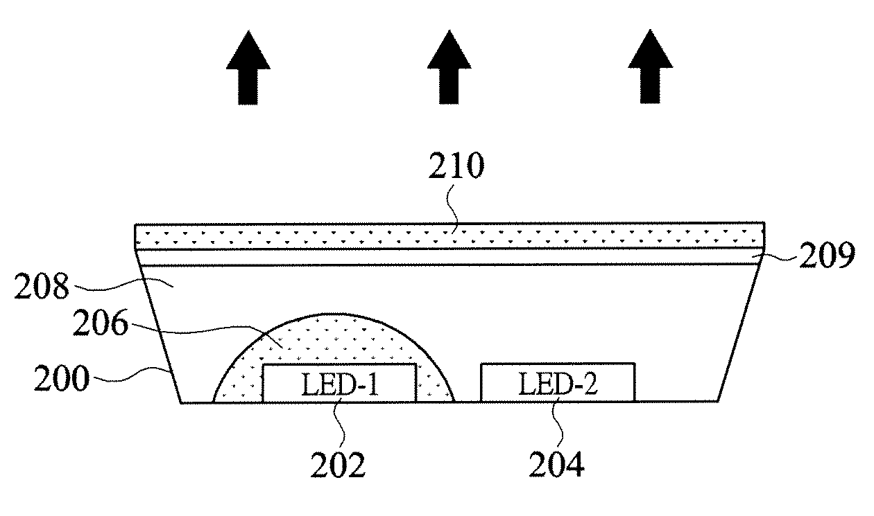
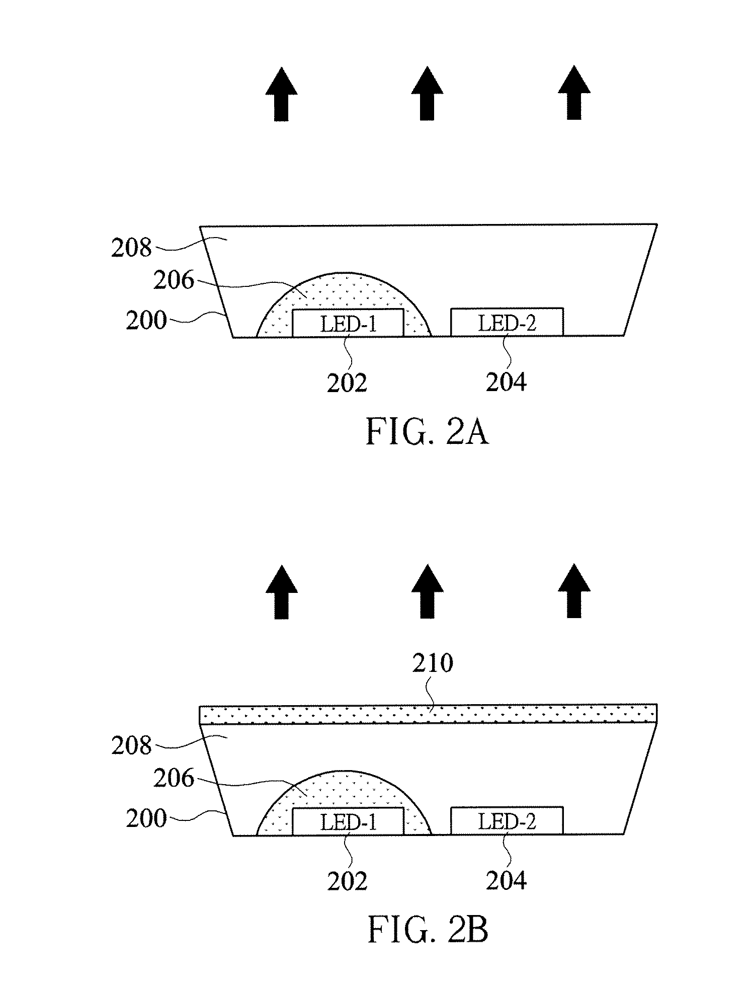
[0028]FIG. 2A is a cross-sectional view showing a light emitting device according to an embodiment of the present invention. The number 200 represents a concave structure with a reflective inner surface (hereinafter, a reflection cup). A first LED group 202 and a second LED group 204 are disposed in the reflection cup 200. The first LED group 202 includes at least one blue light LED which can emit light with a dominant wavelength in a range between 400 nm and 480 nm; and the ...


PUM


Abstract

A light emitting device comprises two light-emitting diode (LED) groups, a group of luminophor layers, and an input terminal. The first LED group includes at least one blue LED emitting light having a dominant wavelength in a range between 400 nm and 480 nm, and the second LED group includes at least one red-orange LED emitting light having a dominant wavelength in a range between 610 nm and 630 nm. The group of luminophor layers, which are selected from one of silicates, nitrides, and nitrogen oxides, are positioned above the first LED group and partially converts the light emitted by the first LED group into light having a dominant wavelength in a range between 500 nm and 555 nm. The input terminal is connected to the two LED groups for providing desired electric energy thereto.

Description

CLAIM OF PRIORITY[0001]This application claims the priority benefit of Taiwan Application Serial Number 98112514, filed on Apr. 15, 2009. All disclosure of the Taiwan application is incorporated herein by reference.BACKGROUND OF THE INVENTION[0002]1. Field of the Invention[0003]The present invention relates to an LED (light-emitting diode) light emitting device. Preferably, the present invention relates to an LED light emitting device with high color rendering index (hereinafter, CRI) and high luminescence efficiency.[0004]2. Description of Related Art[0005]In recent years, blue light LEDs are often combined with fluorescent materials to produce light emitting devices which can emit white light. Such light emitting devices are often used as backlight sources of LCD monitors, traffic signals, illuminated switches, or indicators. Moreover, since the LEDs taken as light sources in the light emitting devices only require a low current to operate, the light emitting devices can considera...

Claims


Application Information

Patent Timeline
Patent Type & Authority Patents(United States)
IPC IPC(8): H05B41/16F21V9/40
CPCH01L25/0753H01L33/44H01L33/50H01L33/54H01L33/56H01L2924/0002H01L2224/48091H01L2224/8592H01L2924/00014H01L2924/00H01L2924/181H01L2924/00012
Inventor LIU, WEN-HUANGDOAN, TRUNG TRITRAN, CHUONG ANH
Owner SEMILEDS OPTOELECTRONICS CO LTD
Why Eureka
Try Eureka