Detecting unwanted components in a computer system based on EMI fingerprints obtained through an insertable device

Active Publication Date: 2020-06-25
ORACLE INT CORP
View PDF0 Cites 0 Cited by
  • Summary
  • Abstract
  • Description
  • Claims
  • Application Information

AI Technical Summary

Benefits of technology

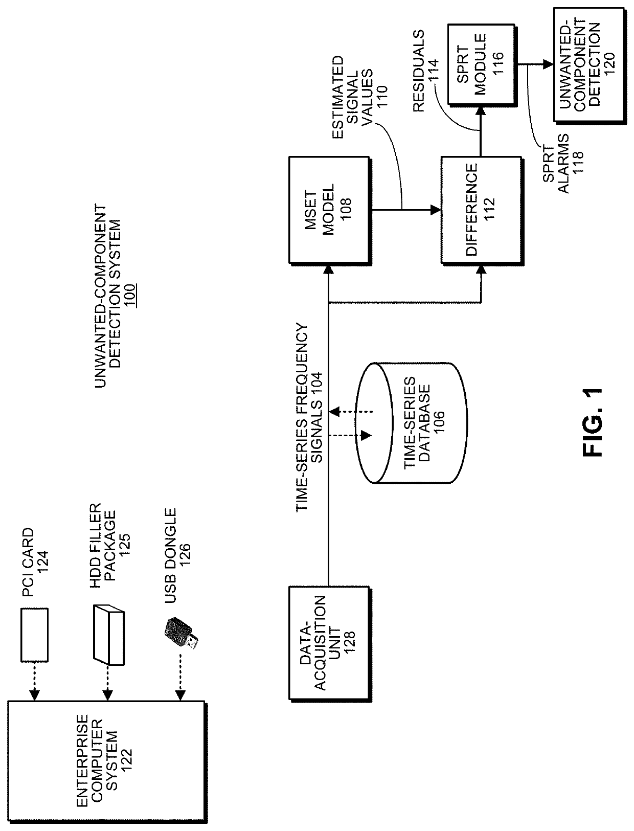
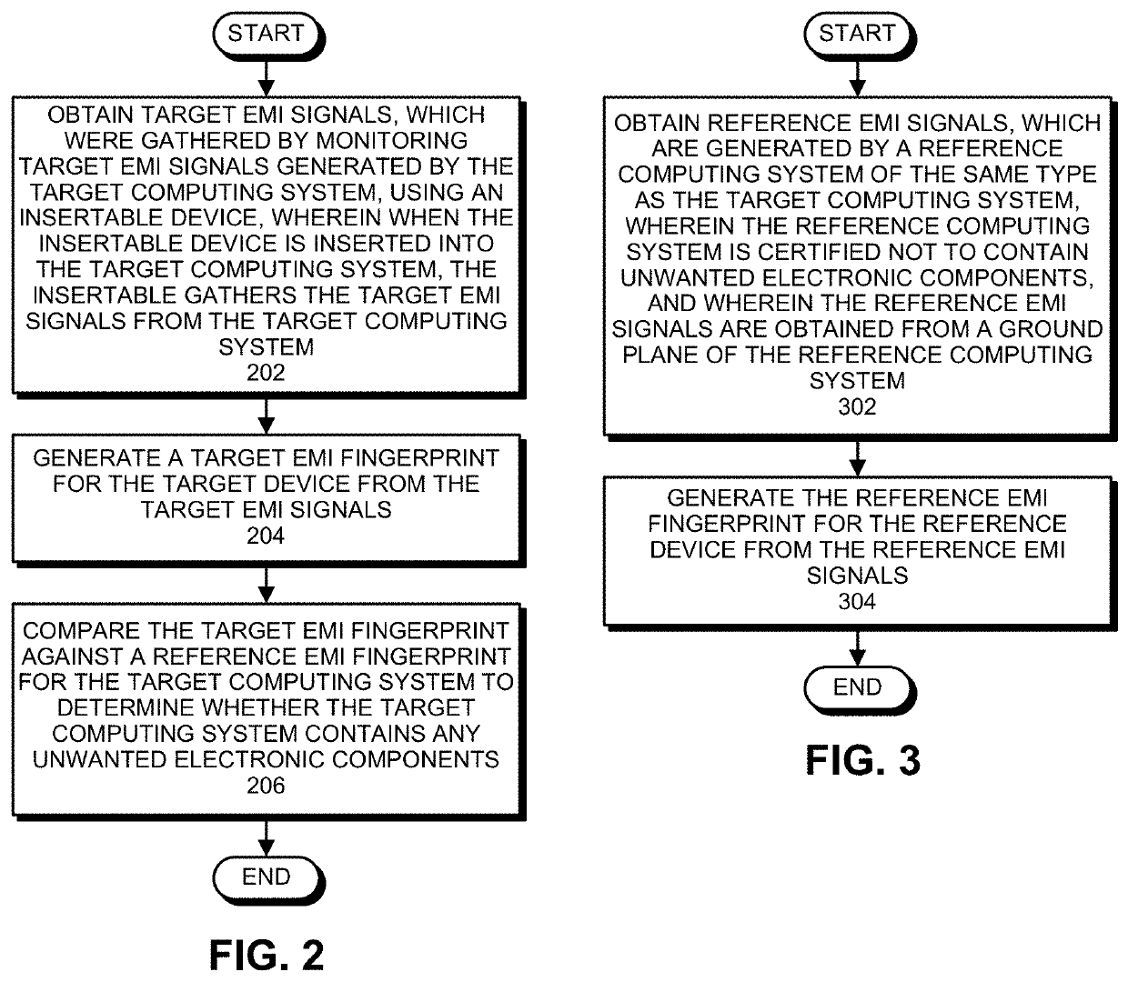
The disclosed embodiments provide a system for detecting unwanted electronic components in a target computing system. The system uses an insertable device to gather target EMI signals from the target computing system and generates a target EMI fingerprint from those signals. The system then compares the target EMI fingerprint against a reference EMI fingerprint for the target computing system to determine if it contains any unwanted electronic components. The insertable device can be a USB dongle, PCI card, or HDD filler package, and can be designed for a specific frequency range. The system can also use an SDR for communication with a data-acquisition unit. The technical effect of this patent is to provide a reliable and effective way to detect and prevent unauthorized electronic components from entering a target computing system.

Problems solved by technology

Unwanted electronic components, such as spy chips, mod chips or counterfeit components, are beginning to cause problems in enterprise computer systems.
Counterfeit components also create problems because they often perform poorly, or fail within a short period of time.
However, a major challenge involved in using such a handheld wand is to ensure that the position and orientation of the handheld wand with respect to the monitored system is similar to that used while monitoring a certified golden system, which contains no unwanted electronic components.
Otherwise, variability in the position and orientation of the handheld wand will adversely affect the rate of false-positives and the rate of missed alarms.
However, this will not help to detect unwanted components in the large installed base of existing enterprise computer systems, which do not possess such integrated antennas.

Method used


Image

  • Detecting unwanted components in a computer system based on EMI fingerprints obtained through an insertable device
  • Detecting unwanted components in a computer system based on EMI fingerprints obtained through an insertable device
  • Detecting unwanted components in a computer system based on EMI fingerprints obtained through an insertable device

Examples


Embodiment Construction

[0023]The following description is presented to enable any person skilled in the art to make and use the present embodiments, and is provided in the context of a particular application and its requirements. Various modifications to the disclosed embodiments will be readily apparent to those skilled in the art, and the general principles defined herein may be applied to other embodiments and applications without departing from the spirit and scope of the present embodiments. Thus, the present embodiments are not limited to the embodiments shown, but are to be accorded the widest scope consistent with the principles and features disclosed herein.

[0024]The data structures and code described in this detailed description are typically stored on a computer-readable storage medium, which may be any device or medium that can store code and / or data for use by a computer system. The computer-readable storage medium includes, but is not limited to, volatile memory, non-volatile memory, magneti...


PUM


Abstract

The disclosed embodiments provide a system that detects unwanted electronic components in a target computing system. During operation, the system obtains target electromagnetic interference (EMI) signals, which were gathered by monitoring EMI signals generated by the target computing system, using an insertable device, wherein when the insertable device is inserted into the target computing system, the insertable device gathers the target EMI signals from the target computing system. Next, the system generates a target EMI fingerprint from the target EMI signals. Finally, the system compares the target EMI fingerprint against a reference EMI fingerprint for the target computing system to determine whether the target computing system contains any unwanted electronic components.

Description

RELATED APPLICATION[0001]This application claims priority under 35 U.S.C. § 119 to U.S. Provisional Application No. 62 / 782,188, entitled “Insertable-Device EMI-Fingerprint Characterization and Security Assurance Certification for Enterprise Servers and Storage Systems” by the same inventors as the instant application, filed on 19 Dec. 2018, the contents of which are incorporated by reference herein.BACKGROUNDField[0002]The disclosed embodiments generally relate to techniques for detecting unwanted electronic components in an enterprise computing system. More specifically, the disclosed embodiments relate to a technique that detects unwanted electronic components, such as spy chips, mod chips or counterfeit electronic components, in an enterprise computing system based on EMI fingerprints gathered through an insertable device.Related Art[0003]Unwanted electronic components, such as spy chips, mod chips or counterfeit components, are beginning to cause problems in enterprise computer ...

Claims


Application Information

Patent Timeline
IPC IPC(8): G06F21/56G06F21/71G01R31/28G06F17/14
CPCG06F21/71G06F21/567G01R31/2813G06F17/142G06F21/566
Inventor LEWIS, ANDREW J.GROSS, KENNY C.DAYRINGER, MICHAEL H.S.WANG, GUANG C.
Owner ORACLE INT CORP
Why Eureka
Try Eureka