Driving method for display

a technology of display signal and driving method, which is applied in the direction of instruments, static indicating devices, etc., can solve the problems of uneven brightness, limited area (i.e., non-display area) where components originally arranged on the front of the display are located, and the difficulty of improving the uniformity of display brightness of the conventional display, so as to achieve the effect of improving the uniformity of display brightness

Inactive Publication Date: 2020-06-25
BAE SYST INFORMATION & ELECTRONICS SYST INTERGRATION INC +1
View PDF0 Cites 1 Cited by
  • Summary
  • Abstract
  • Description
  • Claims
  • Application Information

AI Technical Summary

Benefits of technology

[0003]Therefore, the invention provides a display driving method to improve the uniformity of the display brightness.

Problems solved by technology

However, when the display area is increased, the area (i.e., the non-display area) where the components originally arranged on the front of the display are located will be limited.
For example, as the display area increases, the boundary between the display area and the non-display area will change, resulting in the need to adjust the wirings in the display area, and the brightness may be uneven during display.
Therefore, how to improve the uniformity of the display brightness of the conventional display has become an important issue.

Method used


Image

  • Driving method for display
  • Driving method for display
  • Driving method for display

Examples


Embodiment Construction

[0016]Reference will now be made in detail to the exemplary embodiments, the same or similar reference numbers or components used in the drawings and the embodiments are used to represent the same or similar parts.

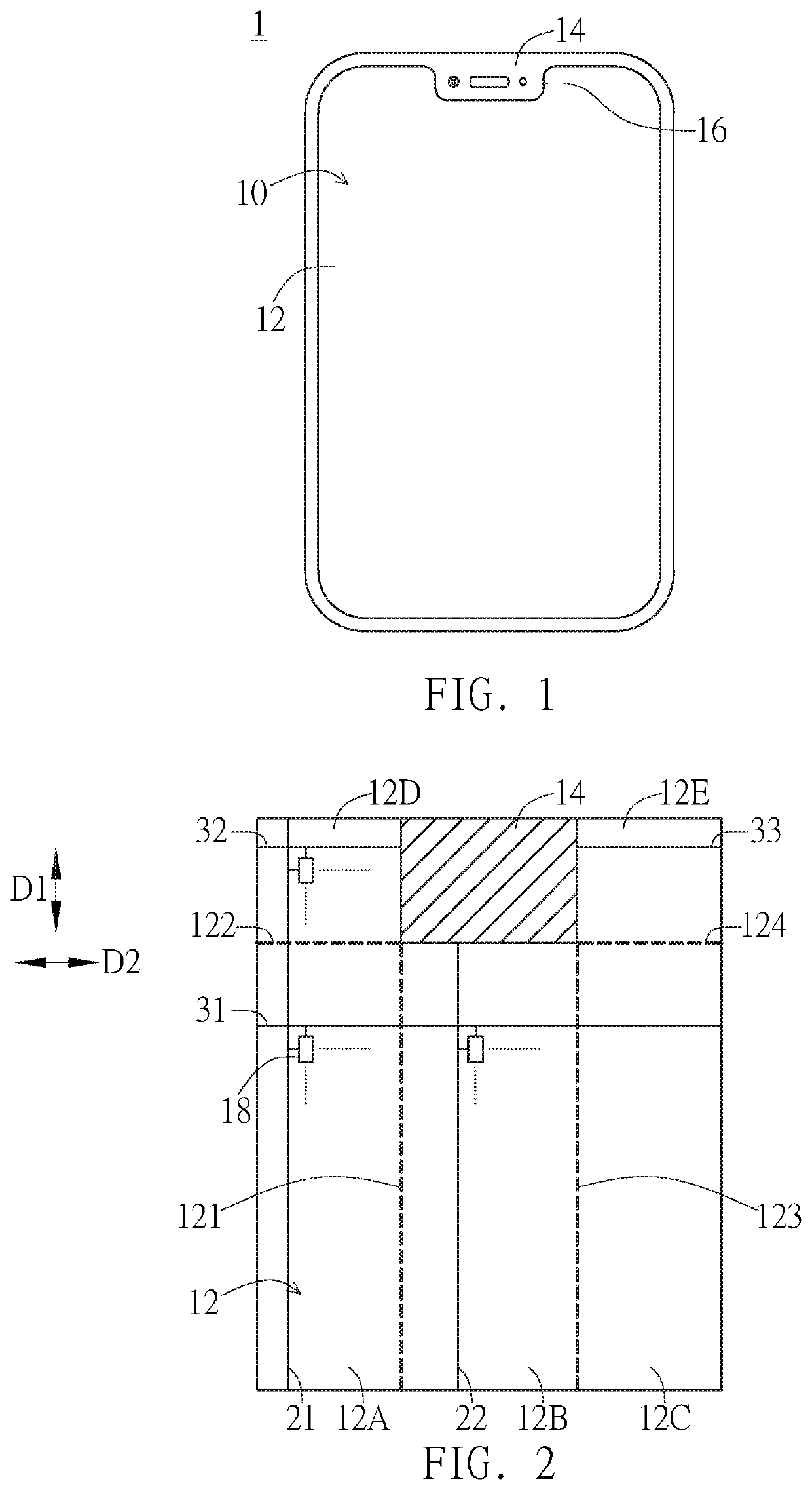
[0017]FIG. 1 is a schematic diagram of an embodiment of a display 1. As shown in FIG. 1, the display 1 has a display surface 10. The display surface 10 includes a display area 12 and a non-display area 14. A concave portion 16 is disposed on a side of the display area 12, and the non-display area 14 is disposed in the concave portion 16. For example, the concave portion 16 is disposed on a side of the display area 12 and extends from the side toward the center of the display area 12. As shown in FIG. 1, among the sides around the display area 12, the side close to the non-display area 14 forms a boundary of a zigzag curve.

[0018]FIG. 2 is a schematic diagram of the display area 12 and the non-display area 14. As shown in FIG. 2, the display area 12 includes an area 12A to a...


PUM


Abstract

A display driving method is disclosed. The display driving method includes the following steps: (A) generating a gate driving signal having a turn-on period by a gate driver; (B) generating a source driving signal by a source driver; the source driving signal has a first waveform corresponding to a first region and has a second waveform corresponding to a second region; (C) outputting, by a controller of a display device, a first control signal to allow the second waveform to be similar to the first waveform in the turn-on period.

Description

BACKGROUND OF THE INVENTION1. Field of the Invention[0001]The invention relates to a display driving method for a display signal; in particular, to a display driving method for a driving integrated circuit.2. Description of the Prior Art[0002]Due to advances in display technology, a range of a display area of a display can be increased. For example, the range of the display area can be larger by the narrow border technology. However, when the display area is increased, the area (i.e., the non-display area) where the components originally arranged on the front of the display are located will be limited. For example, as the display area increases, the boundary between the display area and the non-display area will change, resulting in the need to adjust the wirings in the display area, and the brightness may be uneven during display. Therefore, how to improve the uniformity of the display brightness of the conventional display has become an important issue.SUMMARY OF THE INVENTION[000...

Claims


Application Information

Patent Timeline
Patent Type & Authority Applications(United States)
IPC IPC(8): G09G3/20
CPCG09G2310/0275G09G2320/0233G09G3/20G09G2310/0267G09G2310/06G09G2310/027G09G2320/0223G09G2320/0252
Inventor SHIH, JUN-RENTANG, SHANG-PINGFAN, WEN-TENG
Owner BAE SYST INFORMATION & ELECTRONICS SYST INTERGRATION INC
Why Eureka
Try Eureka