A display panel and its driving method

A display panel and driving method technology, applied in static indicators, instruments, nonlinear optics, etc., to achieve the effects of improving work performance, increasing light transmittance, and saving production costs

Active Publication Date: 2022-07-12
WUHAN CHINA STAR OPTOELECTRONICS TECH CO LTD
View PDF4 Cites 0 Cited by
  • Summary
  • Abstract
  • Description
  • Claims
  • Application Information

AI Technical Summary

Problems solved by technology

[0006] The purpose of the present invention is to provide a display panel and its driving method, which can solve the problems of the existing color filter layer in the display panel

Method used


Image

  • A display panel and its driving method
  • A display panel and its driving method
  • A display panel and its driving method

Examples


Embodiment 1

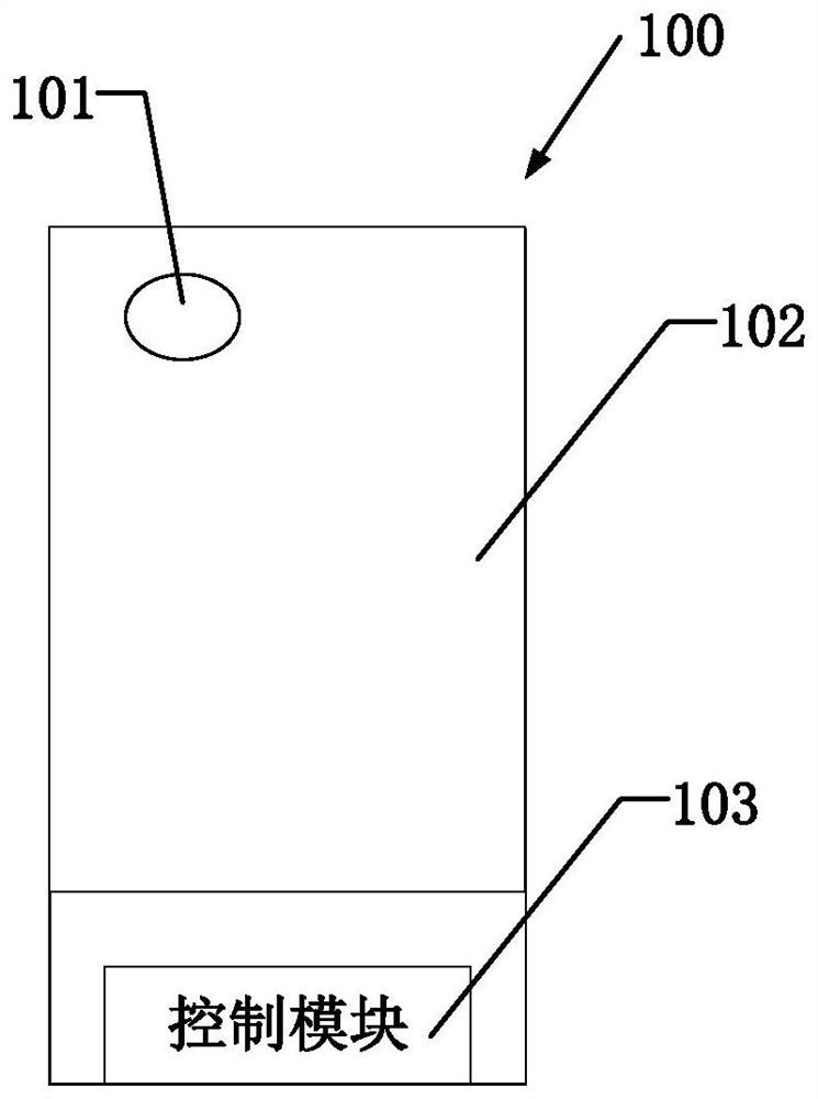
[0049] like figure 1 As shown, this embodiment provides a display panel 100 , which defines a sensing display area 101 and a conventional display area 102 surrounding the sensing display area 101 .

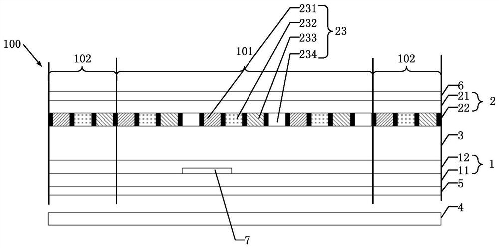
[0050] like figure 2 As shown, the display panel 100 includes an array substrate 1 and a color filter substrate 2 that are disposed opposite to each other.

[0051] like figure 2 As shown, the array substrate 1 includes: a first substrate 11 and an array layer 12 . The color filter substrate 2 includes: a second substrate 21 and a color filter layer 22 .

[0052] The first substrate 11 and the second substrate 21 are disposed opposite to each other. Both the first substrate 11 and the second substrate 21 can be flexible substrates, which have the function of blocking water and oxygen, and both the first substrate 11 and the second substrate 21 have good impact resistance, which can effectively protect the display panel 100 . The materials of the first substrate 11 and the ...

Embodiment 2

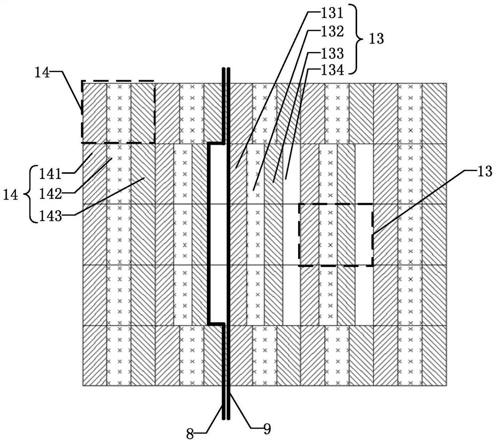
[0069] like Image 6 As shown, Embodiment 2 includes most of the technical features of Embodiment 1, and the difference between Embodiment 2 and Embodiment 1 is that the white sub-pixels 134 of at least two first pixel units 13 are disposed adjacent to each other. In this embodiment, arranging the white sub-pixels 134 adjacent to each other can increase the amount of light reaching the sensing device 7 in this part, which facilitates the rapid operation of the sensing device 7, speeds up the recognition speed of the fingerprint recognition sensor in the sensing device 7, and improves the transmission speed. The photographing effect of the camera in the sensing device 7 is displayed.

Embodiment 3

[0071] like Figure 7 As shown, Embodiment 3 includes most of the technical features of Embodiment 1. The difference between Embodiment 3 and Embodiment 1 is that the first pixel unit 13 of Embodiment 3 further includes: a first red sub-pixel 131, a A green sub-pixel 132, a first blue sub-pixel 133, and three white sub-pixels 134; the three white sub-pixels 134 are respectively disposed at the end of the first red sub-pixel 131, the third The end of a green sub-pixel 132 and the end of the first blue sub-pixel 133 . The first signal line 8 and the second signal line 9 are both gate lines. The first signal line 8 connects the control module 103 and the white sub-pixels 134 in the first pixel unit 13 ; the second signal line 9 connects the control module 103 and the first pixel unit 13 (in this embodiment, the second signal line 9 controls the first red sub-pixel 131, the first green sub-pixel 132 and the first blue sub-pixel 133).


PUM


Abstract

The present invention relates to a display panel and a driving method thereof. A white sub-pixel is added to a first pixel unit of an array substrate in a sensing display area, and a white sub-pixel is added to a first color resist unit of a color filter substrate in the sensing display area. The color resistance uses the full light transmission characteristics of the white sub-color resistance to improve the light transmittance of the sensing display area, improve the light intensity of the sensing device reaching the sensing display area, and improve the working performance of the sensing device.

Description

technical field [0001] The present application relates to the field of display technology, and in particular, to a display panel and a driving method thereof. Background technique [0002] Liquid crystal display (English full name: Liquid Crystal Display, abbreviation: LCD). The liquid crystal display is based on the liquid crystal material as the basic component. The liquid crystal material is filled between two parallel plates, and the arrangement of the molecules inside the liquid crystal material is changed by voltage, so as to achieve the purpose of shading and transmitting light, so as to display different shades and scattered patterns. image. [0003] At present, liquid crystal displays have been widely used in people's lives, such as display screens of mobile phones, computers, and televisions. With the development of display technology and people's demand for progress in display technology, full-screen displays with high screen-to-body ratio and their application ...

Claims


Application Information

Patent Timeline
Patent Type & Authority Patents(China)
IPC IPC(8): G02F1/133G02F1/1335G09G3/36
CPCG02F1/13306G09G3/3607G02F1/133514
Inventor 李雪云
Owner WUHAN CHINA STAR OPTOELECTRONICS TECH CO LTD
Why Eureka
Try Eureka