Trolley coupling structure

Active Publication Date: 2020-07-02
NANSIN CO LTD
View PDF3 Cites 0 Cited by
  • Summary
  • Abstract
  • Description
  • Claims
  • Application Information

AI Technical Summary

Benefits of technology

The invention is related to a trolley coupling structure that prevents the locking member from interfering with the base part of the trolleys when not in use. The locking member is fitted and locked in a receiving recess when not in use, ensuring safety and ease of visual confirmation. The locking member automatically locks when the trolleys are coupled, preventing unintentional unlocking and vibration. The technical effects are improved safety and ease of use.

Problems solved by technology

However, in such coupling, there is a risk that vertical vibration caused when the trolleys get over a step leads to uncoupling.
Further, at the time of achieving the coupling with the use of a different part such as a pin, the uncoupling is likewise apt to occur since the base parts are simply locked, and whether the coupling has been achieved cannot be determined by seeing from outside.

Method used


Image

  • Trolley coupling structure
  • Trolley coupling structure
  • Trolley coupling structure

Examples


example 1

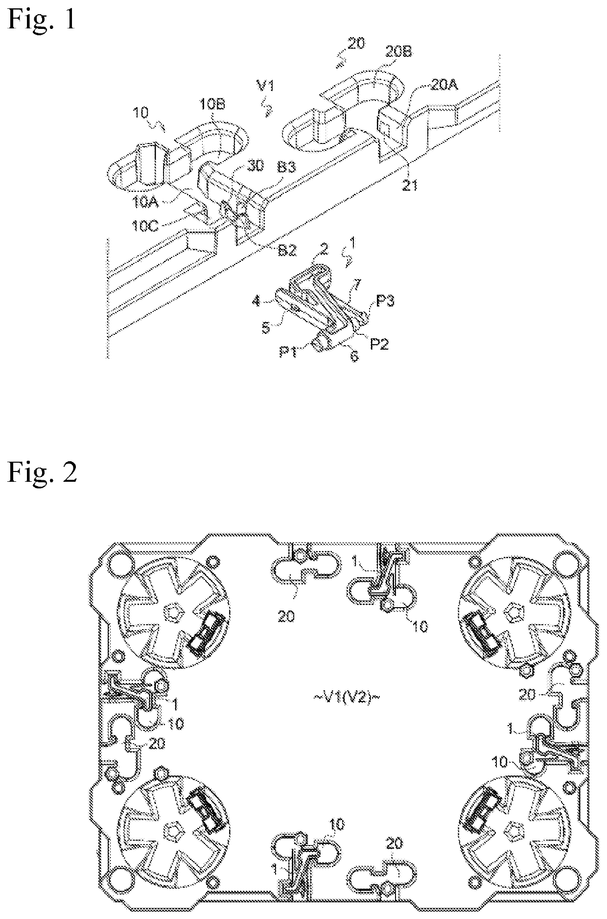
[0033]In one trolley shown in FIG. 1 and FIG. 2, a first receiving recess part 10 is formed on an upper surface of a base part V1 which becomes a cargo bed.

[0034]The first receiving recess part 10 is configured to receive a later-described locking member 1 in such a manner that the locking member 1 does not protrude from the upper surface of the base part V1 when it is not used (when it is folded), and a recess part is opened on an end surface side in a side edge part of the base part V1 to lay the locking member 1 over the trolleys when the locking member 1 is used (developed).

[0035]In the first receiving recess part 10 are formed a first recess part body 10A which extends toward the inner side of the base part V1, a first bent section 10B which crosses the first recess part body 10A on a tip side and laterally bends, and a third bent section 10C which bends to one of left and right sides (the left side in the illustrated example) near a base end, and an upper surface is opened.

[00...


PUM


Abstract

The present invention relates to a novel trolley coupling structure that allows coupling of base parts of trolleys aligned in the vertical or horizontal direction. The present invention provides a trolley coupling structure in which a first receiving recess part is provided in a base part of one trolley, a second receiving recess part is provided in a base part of another trolley, a locking member is pivotally attached to the first receiving recess part, a recess part body and a bent section are formed in the respective first and second receiving recess parts, and retaining of the locking member is achieved by constraining and locking a constraining piece part of the locking member at the bent section.

Description

TECHNICAL FIELD[0001]The present invention relates to an improvement in trolley coupling structure.BACKGROUND ART[0002]In conventional coupling structures of trolleys, there has been known a structure in which a protruding part and a recess part are provided on an edge part of a base part of one trolley, a recess part is provided on an edge part of a base part of the other trolley at a position corresponding to the protruding part, a protruding part is provided on the same at a position corresponding to the recess part, thereby achieving concavo-convex engagement.[0003]However, in such coupling, there is a risk that vertical vibration caused when the trolleys get over a step leads to uncoupling.[0004]Further, at the time of achieving the coupling with the use of a different part such as a pin, the uncoupling is likewise apt to occur since the base parts are simply locked, and whether the coupling has been achieved cannot be determined by seeing from outside.CITATION LISTPatent Liter...

Claims


Application Information

Patent Timeline
IPC IPC(8): B62B5/00
CPCB62B5/00B62B2207/02B62B3/02B60D1/481B60D2001/005B62B5/0093B62B5/0083
Inventor SAITO, AKINORIYAMAGUCHI, KENJIKANAMORI, NAO
Owner NANSIN CO LTD
Why Eureka
Try Eureka