Flow rate adjusting valve

Active Publication Date: 2022-05-19
SMC CORP
View PDF0 Cites 0 Cited by
  • Summary
  • Abstract
  • Description
  • Claims
  • Application Information

AI Technical Summary

Benefits of technology

The flow rate adjusting valve described in this patent allows for easy manual operation of the handle, regardless of the electric motor specifications. The handle can be moved using a push-pull operation, which selectively switches between the rotational operating force of the handle and the driving force of the electric motor. This ensures safety on-site workers as the handle is not rotated by the electric motor. The motive power transmission mechanism allows for the efficient transmission of the selected force to the needle valve. Overall, this valve provides an easy-to-use and safe solution for adjusting flow rates.

Problems solved by technology

There are also cases in which a person performing maintenance of the equipment does not possess the necessary capability to operate the equipment remotely.
If the degree of opening of the flow rate adjusting valve cannot be adjusted manually, cooperation of a system operator or a software engineer must be sought, which is troublesome and time consuming.
However, in the case of using a small-scale electric motor equipped with a speed reducing gear having a large speed reducing ratio, in a state in which the operating unit is connected to the electric motor on a driven side of the speed reducing gear, a situation occurs in which manual operation thereof is difficult.
However, practical implementations thereof have not yet been adequately developed.

Method used


Image

  • Flow rate adjusting valve
  • Flow rate adjusting valve
  • Flow rate adjusting valve

Examples


Embodiment Construction

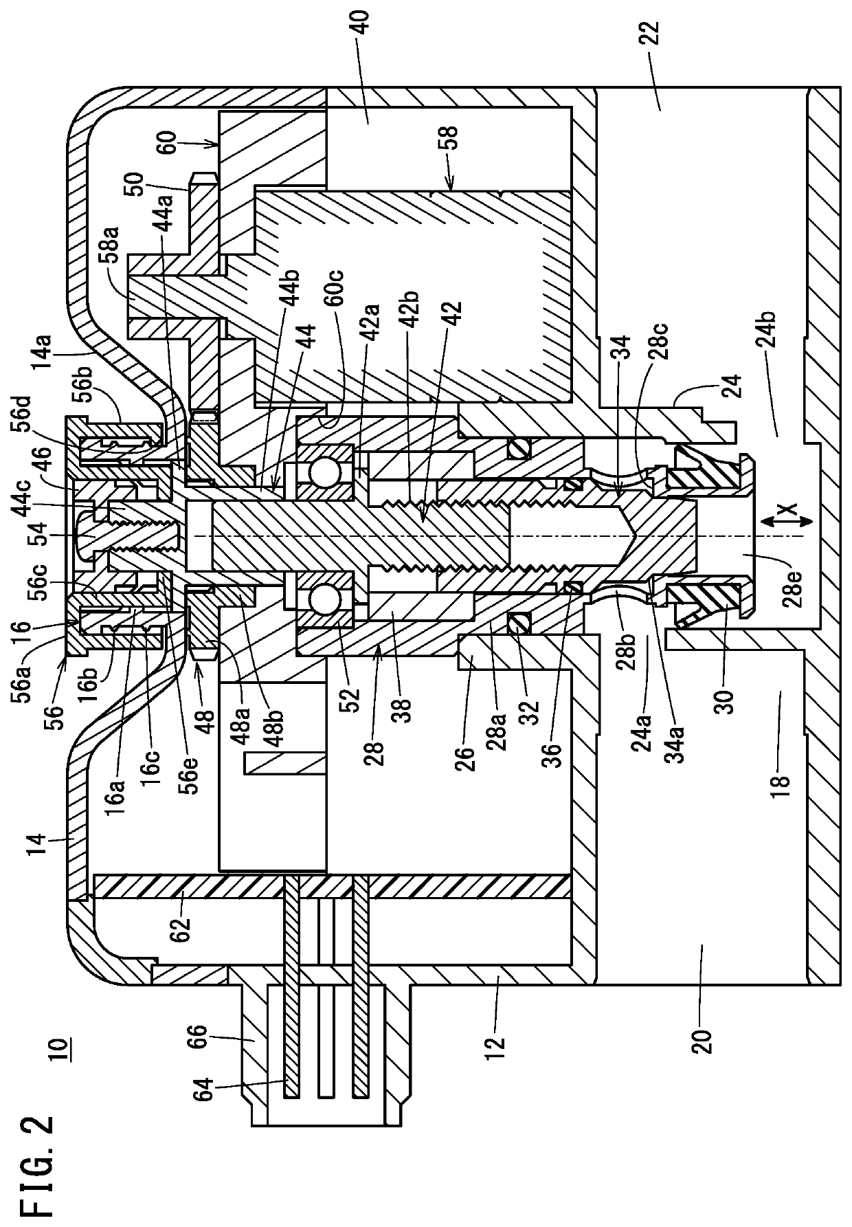
[0019]A flow rate adjusting valve 10 according to an embodiment of the present invention is used to adjust the flow rate of a fluid such as compressed air or the like. In the following description, when the terms in relation to the up, down, left, and right directions are used, for the sake of convenience, such terms refer to the directions shown in the drawings, however, the actual arrangement of the respective component members is not necessarily limited to this feature.

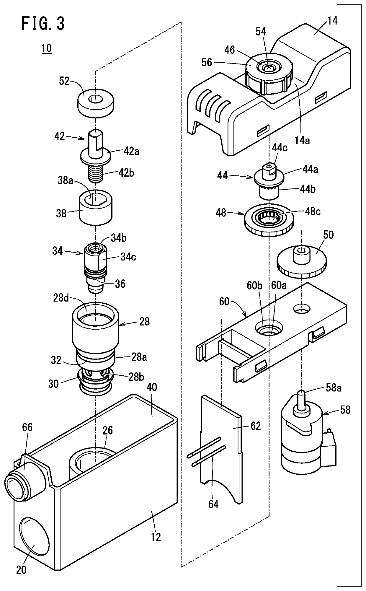
[0020]As shown in FIGS. 1 and 3, the flow rate adjusting valve 10 includes a main body 12, a cover 14, a valve seat body 28, a needle valve 34, a handle 56, a stepping motor (electric motor) 58, and a motive power transmission mechanism. The motive power transmission mechanism is a mechanism that selectively switches between a rotational operating force of the handle 56 and a driving force of the stepping motor 58, and transmits the selected force to the needle valve 34. Details of the motive power transmission mec...


PUM


Abstract

A flow rate adjusting valve, in which a needle valve is arranged so as to face a fluid passage of a main body, is equipped with a handle configured to enable a rotational operation to be performed manually, an electric motor configured to be operated remotely, and a motive power transmission mechanism that selectively switches between a rotational operating force of the handle and a driving force of the electric motor, and to transmit the force to the needle valve. The switching is performed by causing the handle to be moved in a direction of an axis of rotation.

Description

CROSS-REFERENCE TO RELATED APPLICATION[0001]This application is based upon and claims the benefit of priority from Japanese Patent Application No. 2020-189945 filed on Nov. 16, 2020, the contents of which are incorporated herein by reference.BACKGROUND OF THE INVENTIONField of the Invention[0002]The present invention relates to a flow rate adjusting valve that adjusts a flow rate in a fluid passage.Description of the Related Art[0003]Conventionally, as a means for adjusting the speed of a fluid pressure cylinder, a flow rate adjusting valve (speed controller) that is capable of adjusting a flow path area by a manual operation has been known. The flow rate adjusting valve is disposed, for example, in a flow path connecting a fluid pressure cylinder and a fluid supply source, or in a flow path connecting the fluid pressure cylinder and a discharge port.[0004]Further, as shown in JP 5061258 B2, an electric needle valve is also known in which a valve opening degree is adjusted by an ele...

Claims


Application Information

Patent Timeline
IPC IPC(8): F16K31/05F16K1/36
CPCF16K31/05F16K1/36F16K3/246F16K31/53F16K31/50F16K3/314F16K1/38F16K35/027F16K31/60F16K31/04F16K1/52
Inventor OSHIMA, YUTA
Owner SMC CORP
Why Eureka
Try Eureka