Eureka AIR delivers breakthrough ideas for toughest innovation challenges, trusted by R&D personnel around the world.

Substrate treating apparatus and substrate transporting method

Active Publication Date: 2020-07-02
DAINIPPON SCREEN MTG CO LTD
View PDF0 Cites 4 Cited by
  • Summary
  • Abstract
  • Description
  • Claims
  • Application Information

AI Technical Summary

Benefits of technology

[0028]The substrate treating apparatus and the substrate transporting me

Problems solved by technology

However, the substrate treating apparatus described above possesses the following prob

Method used


Image

  • Substrate treating apparatus and substrate transporting method
  • Substrate treating apparatus and substrate transporting method
  • Substrate treating apparatus and substrate transporting method

Examples


Example

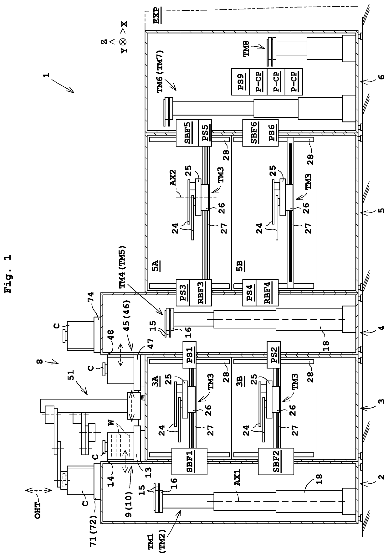
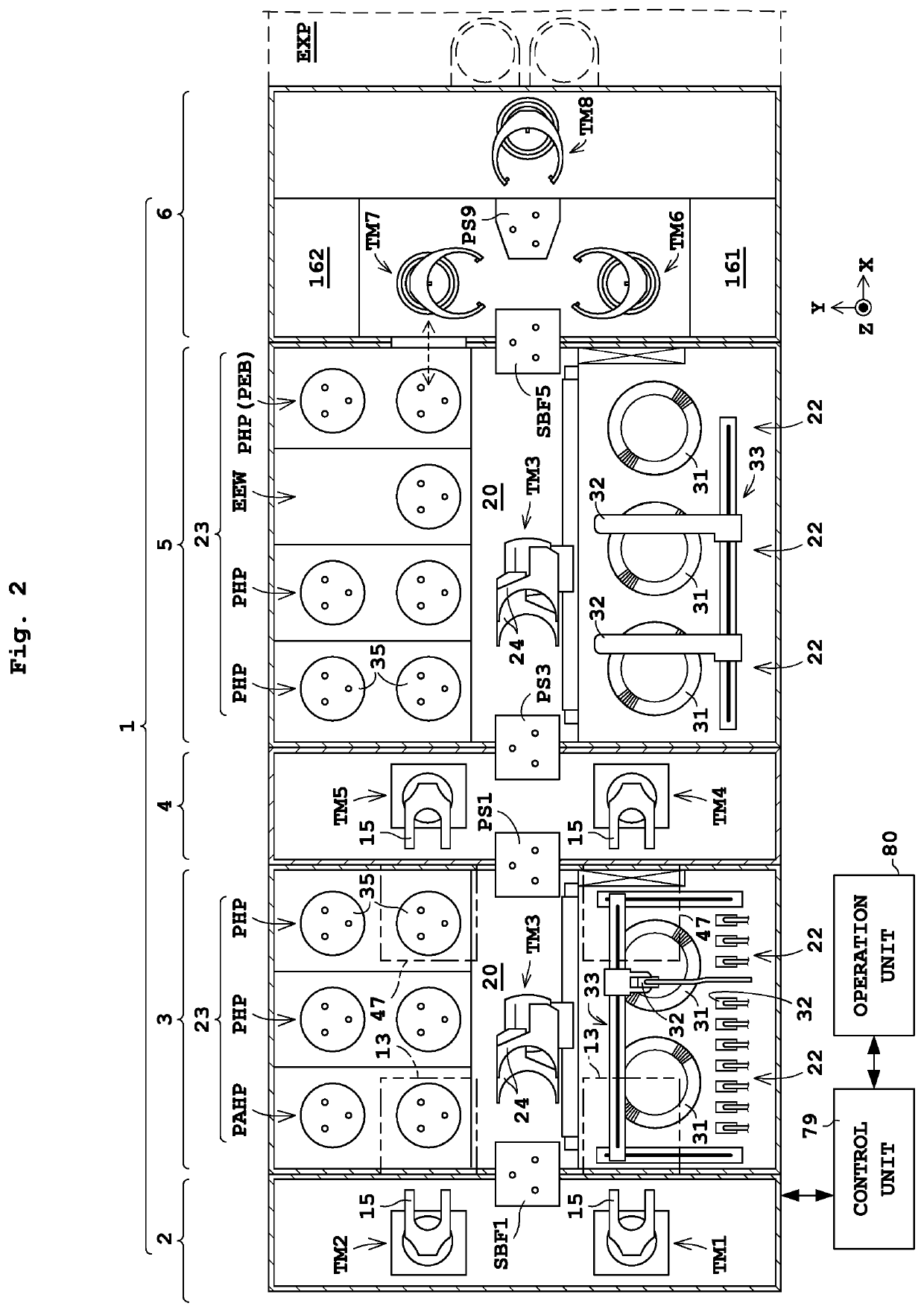
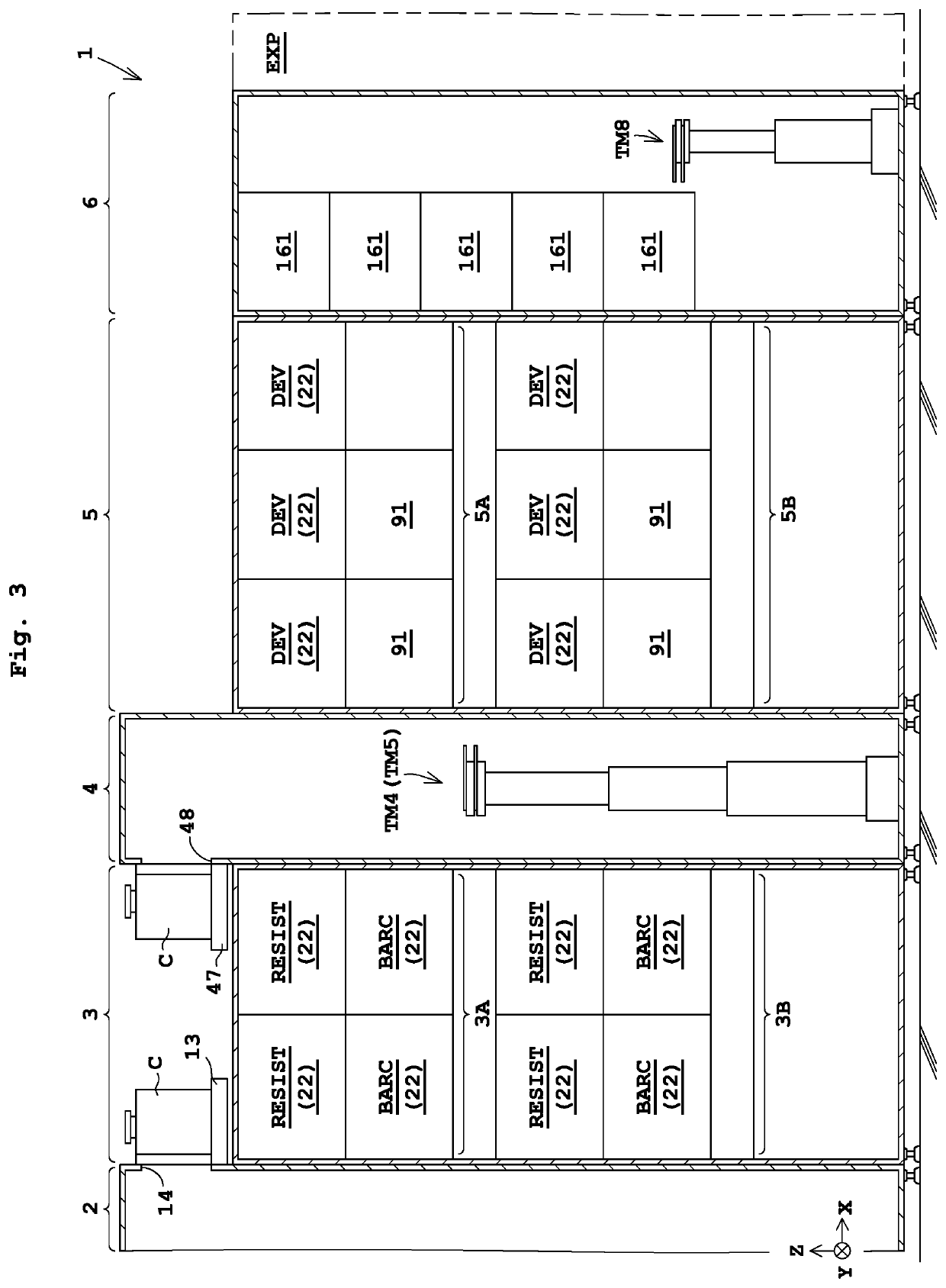
[0048]A first embodiment of the present invention will now be described with reference to the drawings. FIG. 1 is a longitudinal cross-sectional view of a substrate treating apparatus according to a first embodiment. FIG. 2 is a horizontal cross-sectional view of the substrate treating apparatus. FIG. 3 is a right side view of the substrate treating apparatus. FIG. 4 is a left side view of the substrate treating apparatus.

[0049]1>

[0050]Reference is made to FIG. 1 or 2. The substrate treating apparatus 1 includes a first indexer block (first ID block) 2, a coating block 3, a second indexer block (second ID block) 4, a developing block 5, an interface block (IF block) 6, and a carrier buffer device 8. An exposure device EXP is disposed adjacent to the IF block 6. The first ID block 2, the coating block 3, the second ID block 4, the developing block 5, the IF block 6, and the exposure device EXP are arranged linearly in a horizontal direction (X-direction).

[0051]Here in this embodiment...

Example

[0134]A second embodiment of the present invention will now be described with reference to the drawings. Here, the description common to that of the first embodiment is to be omitted.

[0135]In the first embodiment, the substrate treating apparatus 1 takes a substrate W from the carrier C placed on the platform 13 of the first ID block 2 illustrated on the left side of FIG. 1, and accommodates the substrate W into the carrier C placed on the platform 47 of the second ID block 4 illustrated on the right side of FIG. 1. In this regard, such tasks are replaceable with each other. That is, the substrate treating apparatus 1 may take a substrate W from the carrier C placed on the platform 47 of the second ID block 4 illustrated on the right side of FIG. 1, and may accommodate the substrate W into the carrier C placed on the platform 13 of the first ID block 2 illustrated on the left side of FIG. 1.

[0136]FIG. 9 is a right side view illustrating arrangement of a liquid treating units 22 in a...

Example

[0144]A third embodiment of the present invention will now be described with reference to the drawings. Here, the description common to that of the first and second embodiments is to be omitted.

[0145]For instance, in FIG. 3 of the first embodiment, the coating block 3 and the developing block 5 each include two (i.e., a plurality of) treatment layers, and the number of coating-treatment layers in the coating block 3 is equal to the number of developing-treatment layers in the developing block 5. In this regard, the number of coating-treatment layers may be larger than that of developing-treatment layers.

[0146]FIG. 11 is a right side view illustrating arrangement of a liquid treating units 22 in a coating block 3 and a developing block 5 of the substrate treating apparatus according to the third embodiment. The first ID block 2, the coating block 3, the second ID block 4, the developing block 5, and the IF block 6 are arranged in this order as in FIG. 11. The coating block 3 includes...


PUM


Abstract

Disclosed are a substrate treating apparatus and a substrate transporting method. A platform is placed on a first ID block, and a platform is placed on a second ID block. A currently-used carrier platform is provided only on the first ID block. Accordingly, a substrate is transported in both a forward path and a return path between the first ID block and an IF block. According to the disclosure, the substrate is sent in the return path from the IF block to the second ID block disposed between a coating block and a developing block without being transported from the IF block to the first ID block. Consequently, transportation process in the return path by the coating block disposed between the first ID block and the second ID block is reduced. As a result, an entire throughput of a substrate treating apparatus can be enhanced.

Description

CROSS-REFERENCE TO RELATED APPLICATIONS[0001]This application claims priority to Japanese Patent Application No. 2018-248736 filed Dec. 28, 2018, the subject matter of which is incorporated herein by reference in entirety.BACKGROUND OF THE INVENTIONField of the Invention[0002]The present invention relates to a substrate treating apparatus for performing treatment on substrates and a substrate transporting method for the substrate treating apparatus. Examples of substrates include semiconductor substrates, substrates for flat panel displays (FPDs), glass substrates for photomasks, substrates for optical disks, substrates for magnetic disks, ceramic substrates, and substrates for solar cells. Examples of the FPDs include liquid crystal display devices and organic electroluminescence (EL) display devices.Description of the Related Art[0003]A currently-used substrate treating apparatus includes an indexer block (hereinafter, referred to an “ID block”, where appropriate), a coating block...

Claims


Application Information

Patent Timeline
IPC IPC(8): H01L21/677G03F7/20H01L21/67
CPCG03F7/20H01L21/67225H01L21/67766H01L21/67742H01L21/67178H01L21/6715H01L21/67276H01L21/67745H01L21/67727H01L21/67155H01L21/6773H01L21/67733H01L21/67736H01L21/67184H01L21/67161G03F7/70991H01L21/67196
Inventor KUWAHARA, JOJI
Owner DAINIPPON SCREEN MTG CO LTD
Why Eureka
Eureka Blog
Learn More