Climate controlled headgear apparatus

Inactive Publication Date: 2020-07-23
FEHER STEVE
View PDF0 Cites 7 Cited by
  • Summary
  • Abstract
  • Description
  • Claims
  • Application Information

AI Technical Summary

Benefits of technology

[0133]FIG. 89 is a side view of a helmet having optional elastic suspension elements to provide compliance between the user's head shell and the outer shell to reduce rotational trauma to the neck and/or brain.
[0134]FIG. 90 shows a side view of the helmet with a convective headgear internal air

Problems solved by technology

Considerable discomfort can result from wearing a helmet, especially the full-f

Method used


Image

  • Climate controlled headgear apparatus
  • Climate controlled headgear apparatus
  • Climate controlled headgear apparatus

Examples


Example

[0138]Teachings relating to the air conditioned helmets disclosed in U.S. patent application Ser. No. 11 / 252,089 filed Oct. 17, 2005 entitled “AIR CONDITIONED HELMET APPARATUS” which issued as U.S. Pat. No. 7,827,620 on Nov. 9, 2010, and U.S. patent application Ser. No. 10 / 601,964 filed Jun. 23, 2003 entitled “AIR CONDITIONED HELMET APPARATUS” which issued as U.S. Pat. No. 6,954,944 on Oct. 18, 2005, may be employed herein and the disclosures of which are incorporated herein by reference in their entirety.

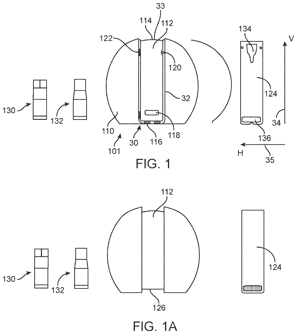
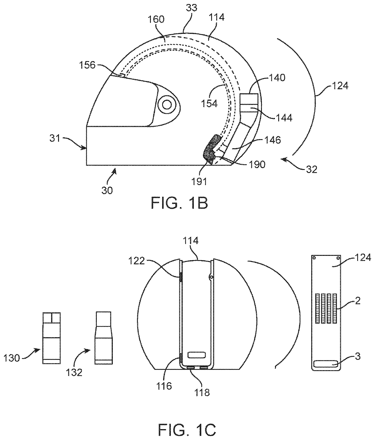
[0139]As used herein and as is commonly known in the art, as depicted in FIGS. 1 and 1B, a helmet 101 has a helmet shell 110 having a first opening 30 of such dimensions as to permit receipt onto the head of a wearer. The helmet shell 110 has a front portion 31 shaped to protect the front face of the wearer, and a rear portion 32 shaped to protect the back of the head of the wearer. The helmet shell 110 has a top portion 33 covering the upper, scalp of the wearer, and a lower porti...


PUM


Abstract

A headgear apparatus for delivering temperature conditioned air including passively or actively cooled, heated, or ventilated air to the interior of a shell is disclosed. A device housing which enshrouds a device for providing temperature conditioned air is placed on a rear portion of the shell. The device housing has air inlets and air rejector vents for delivering fresh air to and removing heated air from the device, and is configured to reduce the heated air from re-entering the device through the air inlets. The headgear apparatus is designed to withstand impact forces without injuring the wearer.

Description

RELATED APPLICATION INFORMATION[0001]The present application claims priority under 35 U.S.C. Section 119(e) to U.S. Provisional Patent Application Ser. No. 62 / 459,563 filed Feb. 15, 2017 entitled “Air Conditioned Helmet, (ACH) & Convective Headgear,” along with PCT App. No. PCT / US18 / 18260, filed Feb. 15, 2018, of the same title, the disclosure of both which are incorporated herein by reference in their entirety.BACKGROUND1. Field[0002]The present application relates in general to headgear. More particularly, the present application is directed to air conditioned and convective helmets and other headgear.2. Description of the Related Art[0003]There are many situations, both work oriented and sport, in which the wearing of a helmet is necessary or highly desirable. Exemplary of but a few instances where wearing a helmet for a relatively long period of time is required are a motorcycle police officer; race car driver; and a military tank driver. Considerable discomfort can result from ...

Claims


Application Information

Patent Timeline
IPC IPC(8): A42B3/28
CPCA42B3/285A42B3/286
Inventor FEHER, STEVE
Owner FEHER STEVE
Why Eureka
Try Eureka