Clamp

a technology of clamping and thread travel, which is applied in the field of clamping, can solve the problems of inconvenient operation for users under the table, potential collision injury hazards, and inaesthetic, and achieve the effects of less overall volume, convenient operation and adjustment, and shortening thread travel

Active Publication Date: 2020-08-06
SYNCMOLD ENTERPRISE CORP
View PDF0 Cites 3 Cited by
  • Summary
  • Abstract
  • Description
  • Claims
  • Application Information

AI Technical Summary

Benefits of technology

[0004]The main object of the present invention is to hide threads of the clamp within itself. The clamp of the present invention is detachable. The initial spacing of the two clamping tongues of the clamp may be pre-adjusted according to various thicknesses of work surfaces. This initial spacing shortens the threads travel required during the clamping process. The screw rod to be operated by the user is arranged on top of the clamp, such that the operating and adjusting are more convenient. Further, the threads are hidden inside the main body of the clamp and the overall volume is smaller. Hence the visual appeal and operating safety are both taken into considerations.

Problems solved by technology

However, the screw rod of the conventional clamp protrudes under the edge of the table.
It is not only inaesthetic but also a potential hazard of collision injury because it is located under the edge of the table.
Further, it is inconvenient for the user to operate under the table.

Method used


Image

  • Clamp
  • Clamp
  • Clamp

Examples


Embodiment Construction

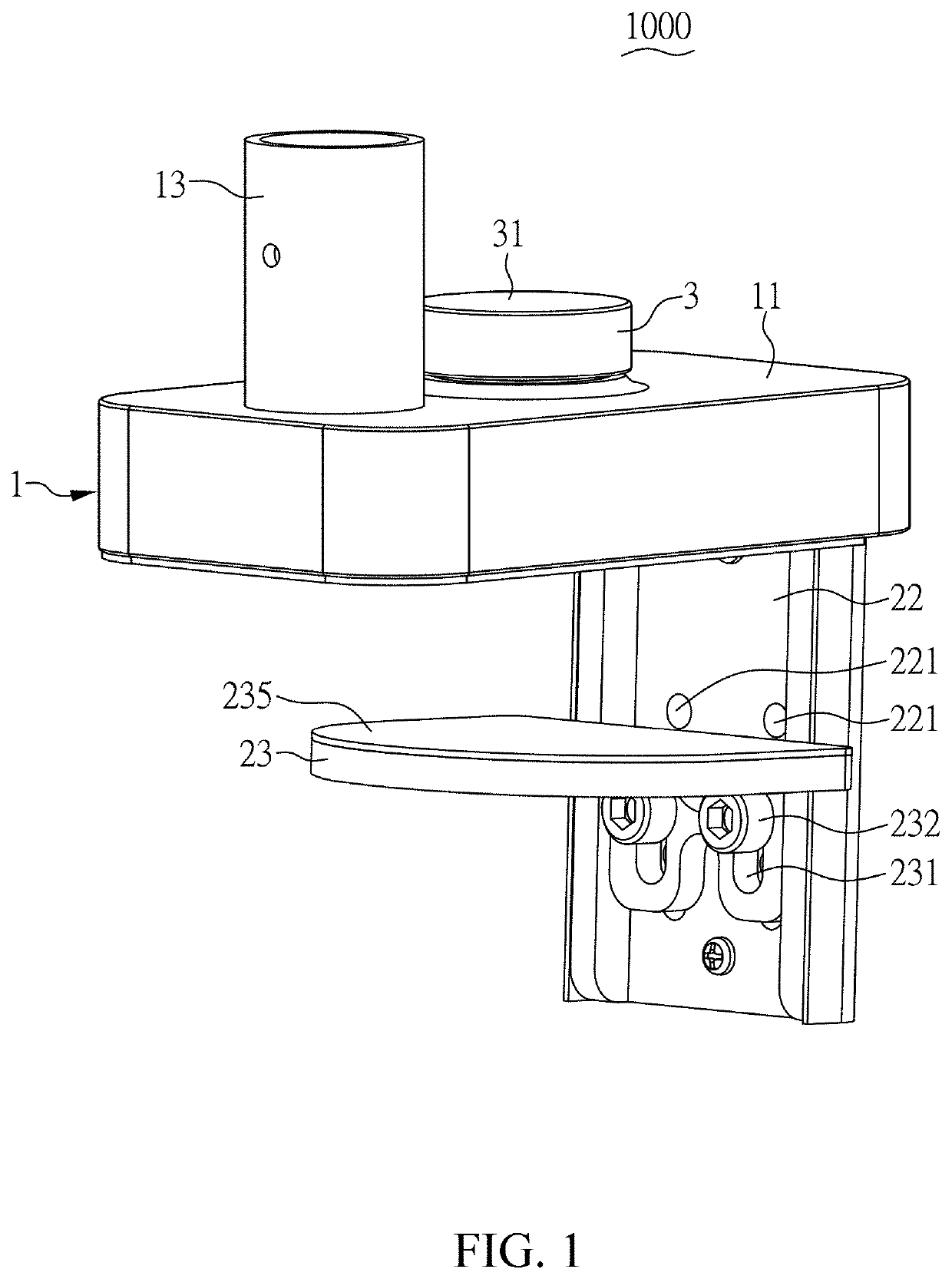
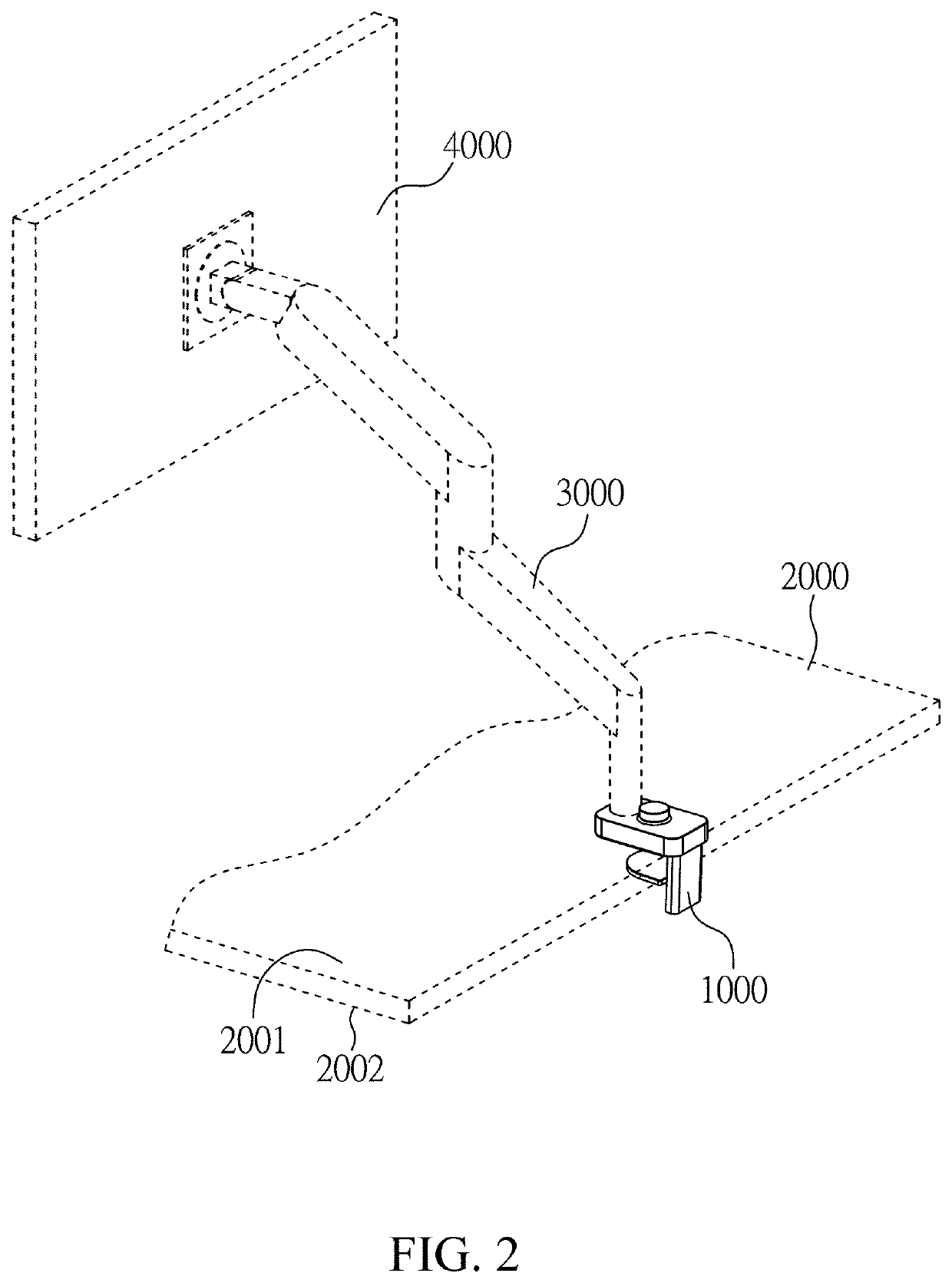
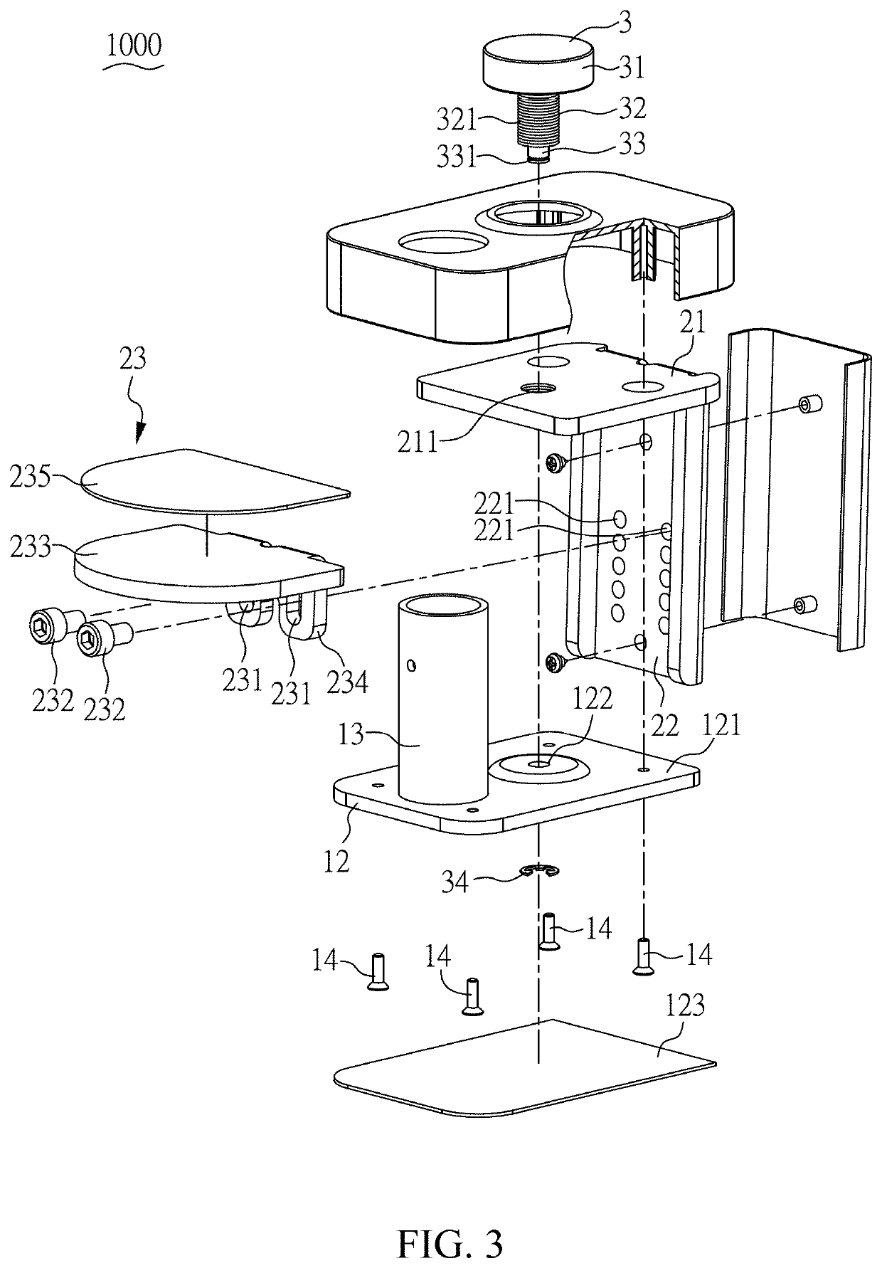
[0024]FIGS. 1, 2, 3 and 6 illustrate a perspective view, an actual use scenario, an exploded view, and a cross-sectional view of an embodiment of the clamp 1000 according to the present invention. The clamp 1000 is utilized to clamp on a board 2000, such as a tabletop, for receiving a supporting arm 3000 that supports a display device 4000. The board 2000 includes an upper surface 2001 and a lower surface 2002. The clamp 1000 has a main body 1, a moving module 2, and a screw rod 3. When the clamp 1000 is clamping on the board 2000, the main body 1 and the screw rod 3 are above the upper surface 2001, and the moving module 2 may move in relation to the board 2000.

[0025]The main body 1 includes a housing 11, a pressing plate 12, a supporting column 13 and four screws 14. The housing 11 is a hollow cover that is fastened to the pressing plate 12 by the screws 14. The housing 11 and the pressing plate 12 collaboratively define a moving space 15. The pressing plate 12 includes a main pla...


PUM


Abstract

A clamp for clamping on a board is provided. The clamp includes a main body, a moving module and a screw rod. The main body includes a housing and a pressing plate to collaboratively define a moving space. The moving module includes a clamping member, a first plate and a second plate connecting with the first plate. The first plate and the pressing plate are disposed in the moving space in parallel. The second plate outwardly extends from the main body. The clamping member is selectively secured to the second plate. The screw rod rotatably and non-shiftably penetrates through the housing and the pressing plate and partially extends outwards the housing, and has threads for fastening to the screw hole of the first plate. When the screw rod rotates, the first plate moves in the moving space, and simultaneously drives the clamping member to move to adjust the distance to the pressing plate.

Description

CROSS REFERENCE TO RELATED APPLICATION[0001]This application claims the benefit of U.S. Provisional Application Ser. No. 62 / 800,068 filed on Feb. 1, 2019, and the benefit of Taiwan Patent Application Serial No. 108207028 filed on Jun. 3, 2019. The entirety of each Application is incorporated herein by reference.BACKGROUND OF THE INVENTION1. Field of the Invention[0002]The present invention is related to a clamp, more particularly, to a clamp clamping onto a board and being disposed with a supporting arm.2. Description of Related Art[0003]Taiwan Patent No. M369599 discloses a conventional supporting arm having a clamp, clamped to the edge of a table for supporting a display. The clamp has a U-shaped clamping seat, a screw rod and a clamping piece. One end of the screw rod for connecting to the clamping piece is disposed through the U-shaped clamping seat. When the clamp is clamping on the edge of the table, the clamping piece contacts with the lower surface of the edge of the table, ...

Claims


Application Information

Patent Timeline
Patent Type & Authority Applications(United States)
IPC IPC(8): F16M13/02F16M11/20
CPCF16M13/022F16M11/20F16B2/10F16B2/12F16M11/04F16M2200/08F16B2/065
Inventor HUANG, CHUN-HAOYEH, CHIEN-CHENG
Owner SYNCMOLD ENTERPRISE CORP
Why Eureka
Try Eureka