Suspension system with optimized damping response

a suspension system and damping technology, applied in the direction of shock absorbers, instruments, cycle equipment, etc., can solve the problems of increased harshness, load management problems, wear and tear of the conventional jounce bumper cushion and related dampers, etc., to reduce wheel travel, reduce harshness, and improve ride quality and handling.

Inactive Publication Date: 2013-06-04
GM GLOBAL TECH OPERATIONS LLC
View PDF25 Cites 25 Cited by
  • Summary
  • Abstract
  • Description
  • Claims
  • Application Information

AI Technical Summary

Benefits of technology

[0017]The present invention is an analytical methodology for the specification of progressive optimal compression damping that enables a motor vehicle suspension system to negotiate severe events, such as potholes, with reduced harshness, yet provides very acceptable ride quality and handling during routine events, such as common road surfaces, limits peak loads on the frame structure, reduces wheel travel, and enables lower trim height.
[0026]With the above conditions, the amount of energy dissipated by the damper is maximized and the total load on the body is minimized whereby a progressive optimal constrained damping function is obtained valid for all displacements of the wheel center from zero to the determined travel length and velocities from U0 to zero.
[0027]Accordingly, it is an object of the present invention to provide an analytical methodology for the specification of progressive optimal compression damping that enables a motor vehicle suspension system to negotiate severe events, such as potholes, with reduced harshness, yet provides very acceptable ride quality and handling during routine events, such as common road surfaces, limits peak loads on the frame structure, reduces wheel travel, and enables lower trim height.

Problems solved by technology

In the art of motor vehicle suspension systems, it is known that a conventional jounce bumper cushion and related dampers can show wear.
This abrupt transfer of jounce force and energy to the frame manifests itself in the passenger compartment as a sharp jolt, which can create load management issues in addition to the discomfort of a rough ride.
Further, in order for the frame to accept such impact loads, the structure of the frame must be engineered for an appropriate strength, which is undesirable from the standpoint of the added vehicle weight such structures must inherently entail.
However, the suspension travel requirements in a vehicle are mainly driven by severe events which generate maximum displacements of the wheel relative to the body.
Trimming a vehicle lower usually increases the level of harshness for an event such as a deep pothole and other severe events.

Method used


Image

  • Suspension system with optimized damping response
  • Suspension system with optimized damping response
  • Suspension system with optimized damping response

Examples


Embodiment Construction

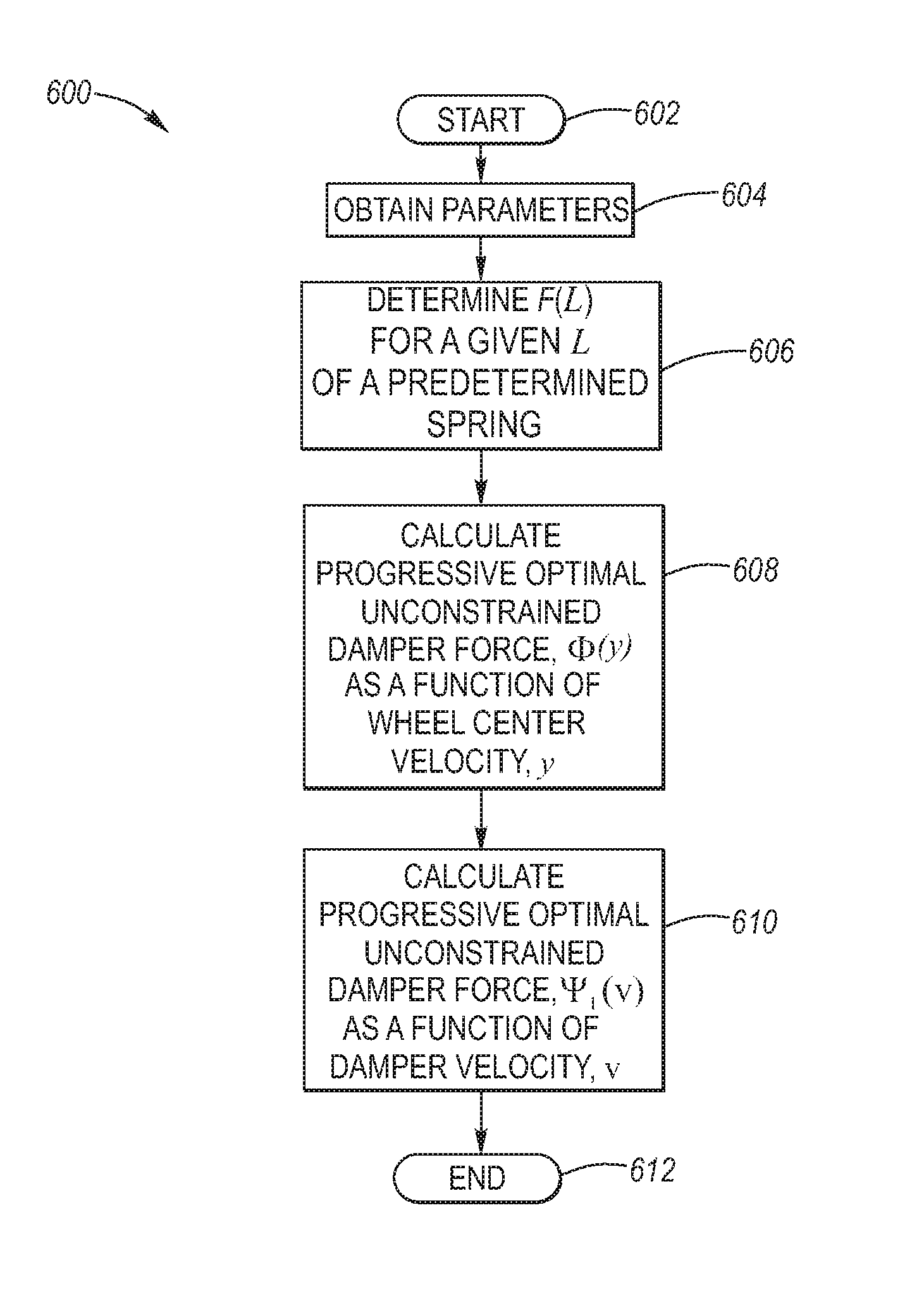
[0042]Referring now to the Drawing, FIGS. 2 through 9 depict various aspects of the methodology according to the present invention to provide optimized damping in a motor vehicle suspension system.

[0043]Generally speaking, the performance of motor vehicles under severe road events is tested using a pavement which includes a series of potholes. For example, a minor pothole would be a shallow pit, and more pronounced pothole would be a deeper pit capable of causing passengers to feel a bounce; and a “severe event” pothole would be a box-shaped drop-off pit with a hard, square edge at the back.

[0044]The following analysis is focused on motor vehicle suspension response to traversal of a “severe event” pothole. During a “severe event” pothole traversal, the wheel first falls into the pothole, followed by the falling body corner, and then, in an already jounced position (compared to nominal trim position), hits a steep bump approximating a step. Tire forces then accelerate the wheel and ...


PUM


Abstract

An analytical methodology for the specification of progressive optimal compression damping of a suspension system to negotiate severe events, yet provides very acceptable ride quality and handling during routine events. In a broad aspect, the method provides a progressive optimal unconstrained damping response of the wheel assembly with respect to the body. In a preferred aspect, the method provides a progressive optimal constrained damping response of the wheel assembly with respect to the body, wherein below a predetermined velocity a conventional damper force is retained.

Description

CROSS-REFERENCE TO RELATED APPLICATIONS[0001]The present regular patent application claims the priority benefit of provisional patent application Ser. No. 60 / 967,209, filed on Aug. 31, 2007.TECHNICAL FIELD[0002]The present invention relates to motor vehicle suspension systems, wherein the motor vehicle body is sprung in relation to each of its wheels via a respective spring-damper combination. More particularly, the present invention relates to a method for providing a progressive optimal damper response to jounce events, including those involving maximum wheel displacements.BACKGROUND OF THE INVENTION[0003]Motor vehicle suspension systems are configured so that the wheels are able to follow elevational changes in the road surface as the vehicle travels therealong. When a rise in the road surface is encountered, the suspension responds in “jounce” in which the wheel is able to move upwardly relative to the frame of the vehicle. On the other hand, when a dip in the road surface is en...

Claims


Application Information

Patent Timeline
Patent Type & Authority Patents(United States)
IPC IPC(8): G06F19/00F16F9/512B62K25/00
CPCB60G17/08F16F9/44B60G2400/202B60G2500/104
Inventor KNOLL, RICHARD J.GOLPE, WILLIAMMOSHCHUK, NIKOLAI K.NAMUDURI, CHANDRA S.NARDI, FLAVIORYU, JIHANNAYAK, RAVIRAJ U.
Owner GM GLOBAL TECH OPERATIONS LLC
Why Eureka
Try Eureka