Method of forming patterns

a pattern and pattern technology, applied in the field of pattern formation, can solve the problems of resist layer degradation, resist description suitable for immersion lithography, and reduce exposure speed, so as to reduce line edge roughness and enhance in-plane uniform line width

Active Publication Date: 2008-12-25
FUJIFILM CORP
View PDF82 Cites 64 Cited by
  • Summary
  • Abstract
  • Description
  • Claims
  • Application Information

AI Technical Summary

Benefits of technology

[0016]The invention aims to solve the aforesaid problems and to provide a pattern formation method that allows reduction in scum appearing after development, and besides, that can ensure reduced line edge roughness, enhanced in-plane uniformity of line width and satisfactory following capability of an immersion liquid, thereby achieving consistent formation of high-accuracy fine patterns for fabrication of high-integration, high-precision electronic devices.

Problems solved by technology

Examples of apparatus utilizing this effect for transfer of fine circuit patterns in semiconductor devices are disclosed in Patent Document 1 (JP-A-57-153433) and Patent Document 2 (JP-A-7-220990), but these documents have no description of resist suitable for immersion lithography.
Since application of immersion lithography to chemical amplification resist brings the resist layer into contact with an immersion liquid at the time of exposure, it is pointed out that the resist layer suffers degradation and ingredients having adverse effects on the immersion liquid are oozed from the resist layer.
More specifically, Patent Document 4 (WO 2004 / 068242) describes cases where the resists aimed at ArF exposure suffer changes in resist performance by immersion in water before and after the exposure, and indicates that such a phenomenon is a problem in immersion lithography.
In addition, there is apprehension that, when an immersion exposure process is carried out using a scanning immersion photolithography machine, reduction in exposure speed occurs unless an immersion liquid moves on with movements of a lens, and has an adverse effect on productivity.
However, the hydrophobicity imparted to resist film brings about unfavorable situations, such as an increase in amount of resist residues (referred to as “scum” too) developed, and degrades image quality of resist.
However, as semiconductor devices become finer, it becomes exceedingly difficult to find suitable combinations of resist composition, developer and so on for formation of totally high-quality patterns.

Method used


Image

  • Method of forming patterns
  • Method of forming patterns
  • Method of forming patterns

Examples


synthesis example 1

Synthesis of Resin (D20)

[0545]In propylene glycol monomethyl ether acetate, 47.2 g of hexafluoroisopropyl acrylate (a product of Wako Pure Chemical Industries, Ltd.) is dissolved, thereby preparing 170 g of a solution having a solid concentration of 20%. To this solution, 8 mole % (3.68 g) of a polymerization initiator V-601 (a product of Wako Pure Chemical Industries, Ltd.) is added. In an atmosphere of nitrogen, the resultant solution is added dropwise over 4 hours to 20.0 g of propylene glycol monomethyl ether acetate heated to 80° C. After the conclusion of dropwise addition, the reaction solution is stirred for 2 hours, thereby obtaining a Reaction Solution (1). After the completion of the reaction, the Reaction Solution (1) is cooled to room temperature, and then added dropwise to a twenty-times greater amount of 8:1 methanol-water solvent mixture. An oily compound thus separated is collected by decantation to yield 24.1 g of the intended Resin (D20).

[0546]The weight average m...

synthesis example 2

Synthesis of Resin (A1)

[0548]In a stream of nitrogen, 20 g of 6:4 (by mass) solvent mixture of propylene glycol mnomethyl ether acetate and propylene glycol monomethyl ether is put in a three-necked flask and heated up to 80° C. (Solvent 1). A monomer mixture composed of γ-butyrolactone methacrylate, hydroxyadamantane methacrylate and 2-methyl-2-adamantyl methacrylate in proportions of 40:25:35 by mole is added to a 6:4 (by mass) solvent mixture of propylene glycol monomethyl ether acetate and propylene glycol monomethyl ether, thereby preparing a 22 mass % monomer solution (200 g). Further, an initiator V-601 (a product of Wako Pure Chemical Industries, Ltd.) is added to and dissolved in the monomer solution in an amount of 8 mole % based on the total monomers. The resultant solution is added dropwise to the Solvent 1 over 6 hours. After the conclusion of dropwise addition, reaction is made to continue at 80° C. for additional 2 hours. The reaction solution obtained is allowed to s...

example 1

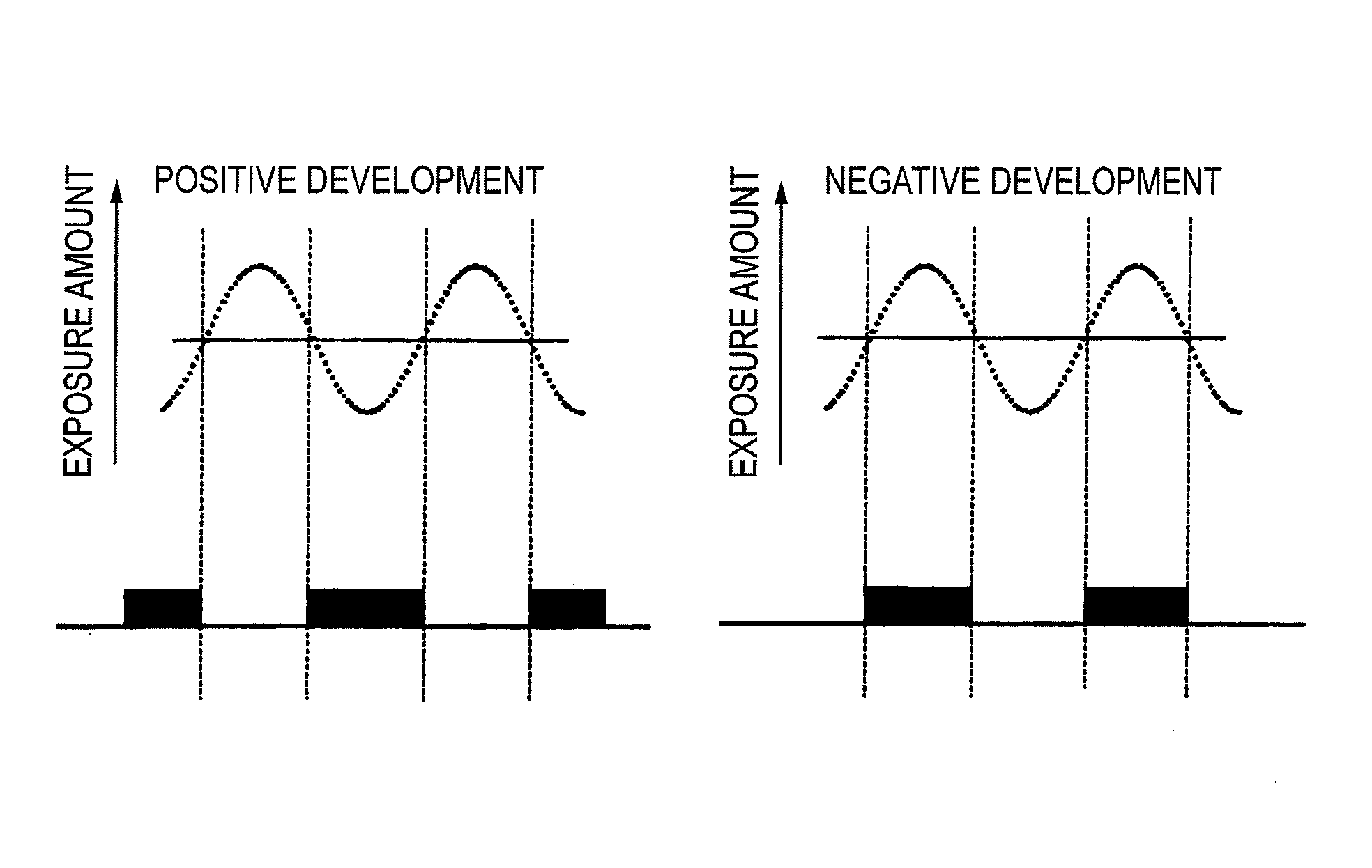
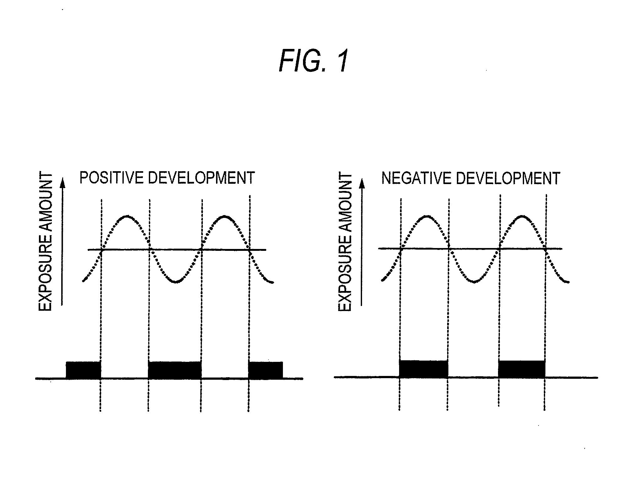
Negative Development

[0563]An organic antireflective film ARC29A (a product of Nissan Chemical Industries, Ltd.) is applied to a silicon wafer surface, and baked at 205° C. for 60 seconds, thereby forming a 78 nm-thick antireflective film. On this film, the resist composition Ra1 is spin-coated, and baked at 120° C. for 60 seconds, thereby forming a 150 nm-thick resist film. The thus obtained wafer is subjected to immersion exposure via a mask for pattern formation, wherein purified water is used as the immersion liquid and PAS5500 / 1250i equipped with a lens of NA=0.85 (made by ASML) is used as an ArF excimer laser scanner. After the exposure, the wafer is spun at revs of 2,000 rpm, and thereby the water remaining on the wafer is removed. Then, the wafer is subjected successively to 60 seconds' heating at 120° C., 60 seconds' development (negative development) with butyl acetate (negative developer), rinse with 1-hexanol, and 30 seconds' spinning at revs of 4,000 rpm. Thus, 80-nm (1:...


PUM

PropertyMeasurementUnit
receding contact angleaaaaaaaaaa
contact angleaaaaaaaaaa
polarityaaaaaaaaaa

Abstract

A method of forming patterns includes (a) coating a substrate with a resist composition for negative development to form a resist film having a receding contact angle of 70 degrees or above with respect to water, wherein the resist composition for negative development contains a resin capable of increasing the polarity by the action of an acid and becomes more soluble in a positive developer and less soluble in a negative developer upon irradiation with an actinic ray or radiation, (b) exposing the resist film via an immersion medium, and (c) performing development with a negative developer.

Description

BACKGROUND OF THE INVENTION[0001]1. Field of the Invention[0002]The present invention relates to a method of forming patterns, which is usable in a production process of semiconductors, such as ICs, manufacturing of circuit boards for liquid crystal displays or thermal heads, and other lithography processes of photofabrication. More specifically, the invention is concerned with a method of forming patters by using a resist composition for negative development and a negative developer preferable used in the lithography process performing light exposure by means of immersion-type projection exposure apparatus.[0003]2. Description of the Related Art[0004]As semiconductor devices have become increasingly finer, progress has been made in developing exposure light sources of shorter wavelengths and projection lenses having higher numerical apertures (higher NAs). Up to now, steppers using as light sources ArF excimer laser with a wavelength of 193 nm and having NA of 1.35 have been develo...

Claims


Application Information

Patent Timeline
Patent Type & Authority Applications(United States)
IPC IPC(8): G03F7/20
CPCG03F7/0392G03F7/2041G03F7/325G03F7/0395G03F7/0397G03F7/11Y10S430/146Y10S430/114G03F7/004G03F7/0045G03F7/0046G03F7/0382G03F7/20H01L21/027H01L21/0271
Inventor TSUBAKI, HIDEAKI
Owner FUJIFILM CORP
Why Eureka
Try Eureka