Electric submersible pump with specialized geometry for pumping viscous crude oil

a submersible pump and viscous fluid technology, applied in the direction of positive displacement liquid engine, wellbore/well accessories, sealing/packing, etc., can solve the problems of pump diameter and temperature rise as oil passes through the pump, and achieve the effect of imparting energy, and minimizing the length of the van

Inactive Publication Date: 2005-02-15
BAKER HUGHES INC
View PDF17 Cites 23 Cited by
  • Summary
  • Abstract
  • Description
  • Claims
  • Application Information

AI Technical Summary

Benefits of technology

Centrifugal pumps impart energy to the fluid being pumped by accelerating the fluid through the impeller. When the fluid leaves the impeller, the energy it contains is largely kinetic and must be converted to potential energy to be useful as head or pressure. In this invention, energy is imparted to the viscous fluid as rapidly as possible by using impeller vane geometry containing exit angles greater than 30 degrees. The use of large exit angles also minimizes vane length. Vane inlet angles in the range of 0 degrees to 30 degrees are used to minimize impact and angle-of-incidence losses. Diffuser vanes in this invention decelerate and direct the viscous fluid to the next pump stage as rapidly as possible using the same philosophy as used in the impeller, i.e. minimizing vane lengths and rapidly transitioning between the diffuser inlet and exit angles.
Inherent in the operation of centrifugal pumps, the energy dissipated as a result of frictional losses is absorbed as heat by the viscous crude oil, resulting in a temperature rise as the oil passes through the pump. The temperature rise in turn lowers the crude oil viscosity. The temperature rise can be significant in an ESP because of the length and number of stages contained in a typical ESP application. The present invention seeks to take advantage of the decreasing viscosity by assembling the pump in zones or modules with the impeller and diffuser geometry in each zone or module optimized for the viscosity and / or NPSH (net positive suction head) conditions of the viscous crude oil passing through that zone. Geometry refers to the configuration of the vanes with respect to the exit angles and number of vanes.
Flow rate varies directly with rotative speed and head or pressure varies with the square of rotative speed in centrifugal pumps. Reducing the impeller diameter minimizes disk friction but reduces the head and flow of the pump. When higher rotative speeds are coupled with vane geometry optimized for viscous pumping, performance per stage is restored and efficiency is further increased by reducing the amount of time in which the impeller and / or diffuser are in contact with the viscous fluids relative to the flow rate of the pump. As a practical limit, rotative speeds will be limited to 10,500 rpm, which corresponds to the speed of a two-pole electric motor operating at a frequency of 180 Hz. The present invention seeks to minimize disk friction by shortening the distance that the viscous fluid must travel as it moves through the pump. At the same time, clearances between rotating and stationary components are optimized to minimize the effect of boundary layer losses on non-pumping surfaces.

Problems solved by technology

The pump diameter can vary, but is limited based upon the fit-up arrangement in the well.
Inherent in the operation of centrifugal pumps, the energy dissipated as a result of frictional losses is absorbed as heat by the viscous crude oil, resulting in a temperature rise as the oil passes through the pump.

Method used


Image

  • Electric submersible pump with specialized geometry for pumping viscous crude oil
  • Electric submersible pump with specialized geometry for pumping viscous crude oil
  • Electric submersible pump with specialized geometry for pumping viscous crude oil

Examples


Embodiment Construction

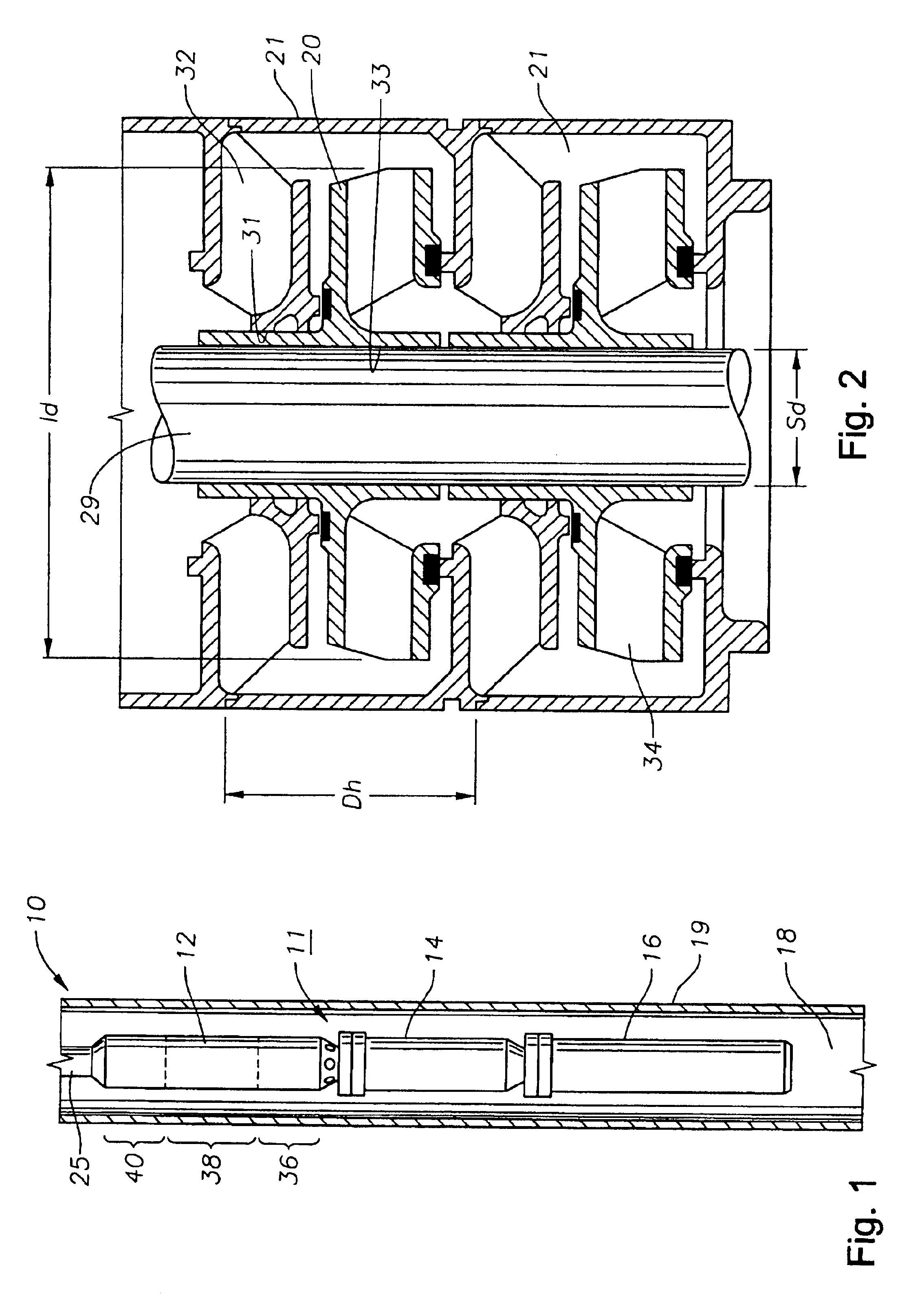
Referring to the drawings, FIG. 1 generally depicts a well 10 with a submersible pump assembly 11 installed within. The pump assembly 11 comprises a centrifugal pump 12 that has a seal section 14 attached to it and an electric motor 16 submerged in a well fluid 18. The shaft of motor 16 connects to the seal section shaft 15 (not shown) and is connected to the centrifugal pump 12. The pump assembly 11 and well fluid 18 are located within a casing 19, which is part of the well 10. Pump 12 connects to tubing 25 that is needed to convey the well fluid 18 to a storage tank (not shown).

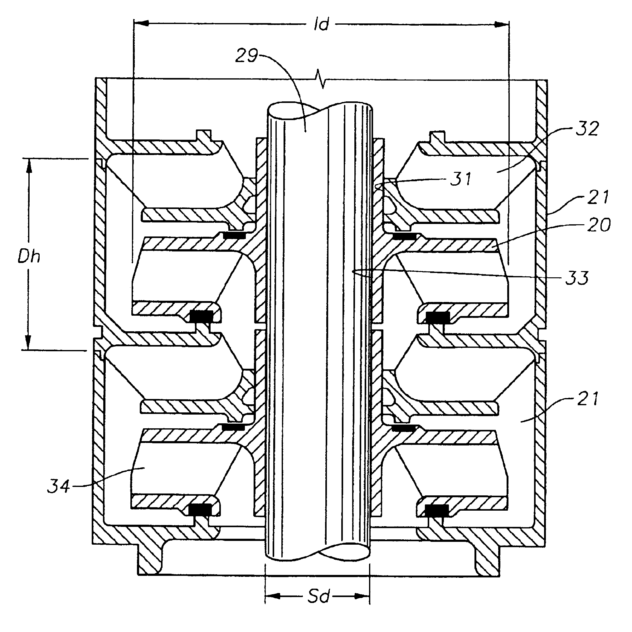
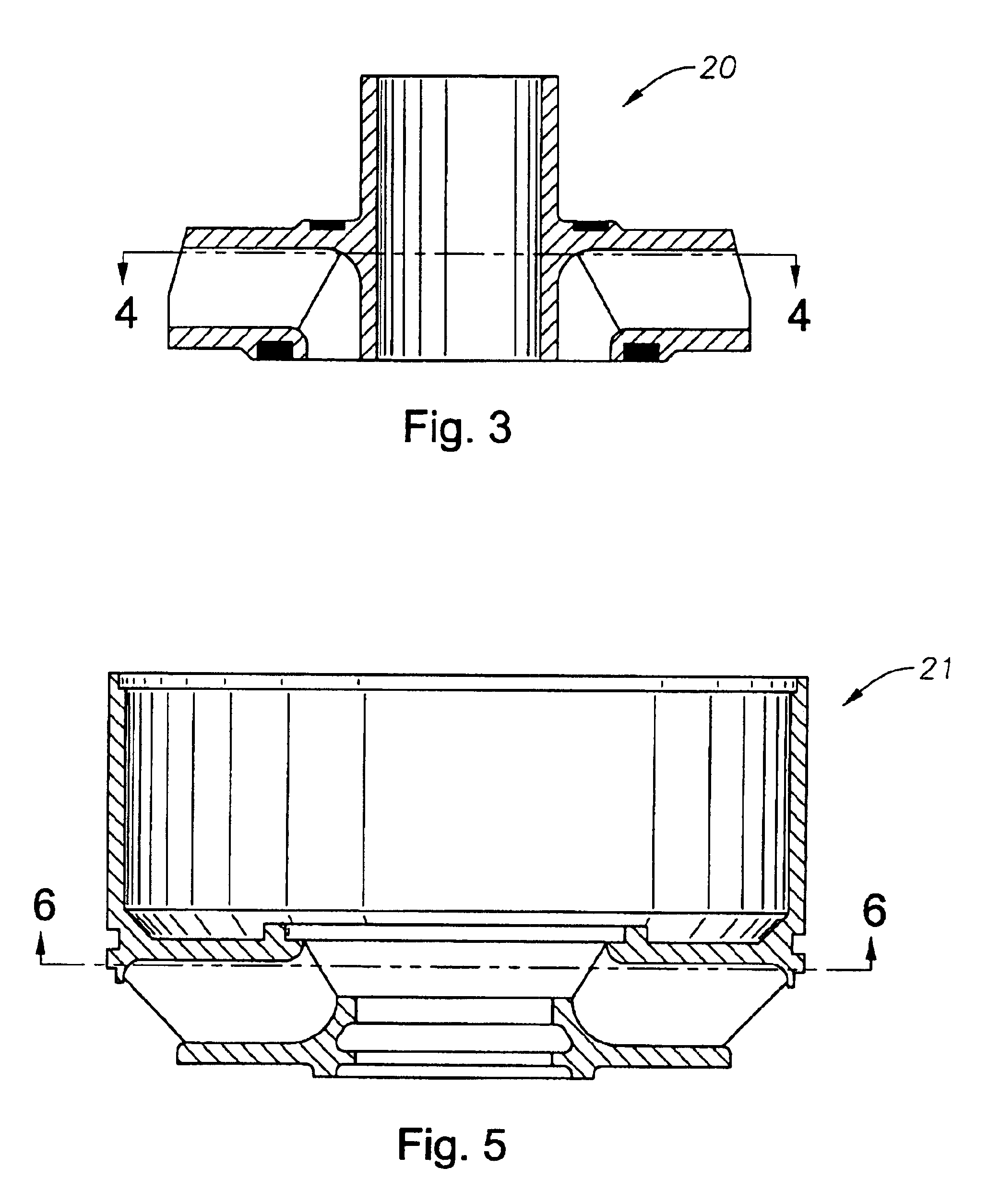
Referring to FIG. 2, centrifugal pump 12 has a housing 27 (not shown in FIG. 2) that protects many of the pump 12 components. Pump 12 contains a shaft 29 that extends longitudinally through the pump 12. Diffusers 21 have an inner portion with a bore 31 through which shaft 29 extends. Each diffuser 21 contains a plurality of passages 32 that extend through the diffuser 21. Each passage 32 is defined by vanes...


PUM


Abstract

A centrifugal pump has impellers for pumping low flow, high viscous materials. The impellers have high exit angles greater than 30 degrees and preferably greater than 50 degrees. The impellers and diffusers have specific geometry that varies with viscosity. The pump has zones of impellers and diffusers with the exit angles and geometry in the zones differing from the other zones. The exit angles decrease and geometry varies in a downstream direction to account for a lower viscosity occurring due to heat being generated in the pump. One design employs small diameter impellers and high rotational speeds.

Description

BACKGROUND OF THE INVENTION1. Field of the InventionThis invention relates in general to electric submersible well pumps. More specifically, this invention relates to submersible well pumps that have an impeller configuration designed for high viscosity fluids and operate at high rotative speeds.2. Description of the Prior ArtTraditionally the use of electric submersible pumps (ESP's) in low flow viscous crude pumping applications has been limited because of low efficiencies inherent with low capacity centrifugal pumps handling viscous fluids. Low efficiencies result from disk friction losses caused by a layer of viscous fluid adhering to the walls of both rotating and stationary components within the pump impeller and diffuser. Viscous fluids are considered herein to be fluids with a viscosity greater than 500 centipoise.Others have made and used ESP's to pump viscous materials. However, most of these attempts have involved either modifying the material to be pumped or controlling ...

Claims


Application Information

Patent Timeline
Patent Type & Authority Patents(United States)
IPC IPC(8): E21B43/12
CPCE21B43/128F04D13/10
Inventor GAY, FARRAL D.JAMES, MARK C.VANDEVIER, JOSEPH E.
Owner BAKER HUGHES INC
Why Eureka
Try Eureka