Cord lock

Active Publication Date: 2020-08-13
RIRI
View PDF0 Cites 2 Cited by
  • Summary
  • Abstract
  • Description
  • Claims
  • Application Information

AI Technical Summary

Benefits of technology

[0013]According to another aspect, there is described a method for assembling a cord lock of the above-indicated type. The method provides for a main body and a corresponding friction member to be provided. Subsequently, a cord is introduced into the through-

Problems solved by technology

The adjustment of the cord with this type of cord lock is quite difficult.
Furthermore, the plate can be cumbersome or heavy.
When the loop of the cord is slackened, there is al

Method used


Image

  • Cord lock
  • Cord lock

Examples


Embodiment Construction

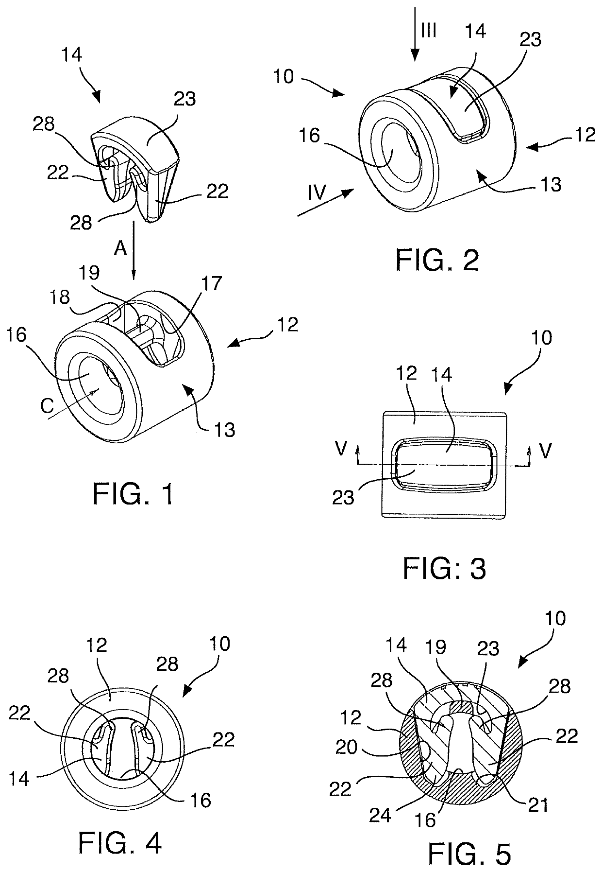
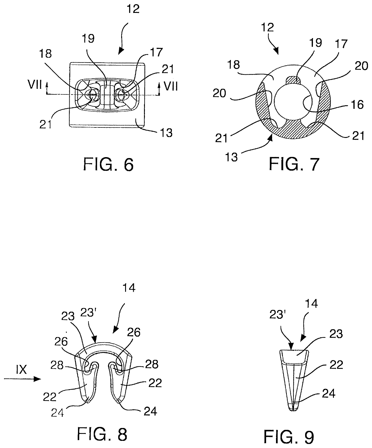
[0025]With reference now to the Figures, a cord lock 10 comprises a main body 12 and a friction member 14. The main body 12 has a through-hole 16, in which during use the cord to be adjusted is introduced, in the direction of the arrow C of FIG. 1. The main body 12 illustrated in the Figures has a cylindrical external formation with an external wall 13 which is substantially cylindrical. Although the cylindrical formation of the cord lock illustrated in the Figures is particularly compact, the external shape of the main body 12 may be of any desired shape, for example, spherical, ovoid, parallelepipedal, cubic, etc. At the outer side, the main body 12 may further be decorated and embellished in different manners, for example, by means of incisions, reliefs, glazing, layers of precious metals, applications of precious stones or pietra dura, and so on. The main body 12 may be produced from metal or metal alloy, for example, zamak, or a plastics material, although the possibility of us...


PUM


Abstract

A cord lock for adjusting the length of a cord includes a main body with a through hole, in which a cord can be inserted. A friction member is blocked in the main body in such a manner that a portion of a tooth thereof narrows the gap of the through-hole in order to limit the sliding of the cord.

Description

CROSS-REFERENCE TO RELATED APPLICATIONS[0001]This claims priority from Italian Application No. 102019000001935, filed Feb. 11, 2019, the disclosure of which is hereby incorporated by reference in its entirety into this application.FIELD OF THE INVENTION[0002]The present invention relates to a cord lock.TECHNOLOGICAL BACKGROUND[0003]Cord locks are typically used to adjust the length of cords, thin strings, resilient cords and the like, for example, in clothing items.[0004]A simple type of cord lock involves a plate which is provided with two holes which are close together and in which there is introduced the cord which is intended to be adjusted and in which a loop is thus intended to be formed. The friction of the cord in the holes of the plate prevents it from sliding. In order to adjust the position of the cord lock, it is necessary to slacken and widen the loop so as to slide the cord in the holes of the plate. The adjustment of the cord with this type of cord lock is quite diffi...

Claims


Application Information

Patent Timeline
IPC IPC(8): F16G11/10F16G11/04
CPCF16G11/103F16G11/101F16G11/044Y10T24/3969
Inventor BREZZI, SIMONEDAL TOSO, DAVIDE
Owner RIRI
Why Eureka
Try Eureka