
Traffic predictions at lane level

a technology of traffic prediction and lane level, applied in the field of traffic prediction, can solve the problems of large difficulty in short-term traffic prediction, high cost of measuring traffic volume, and high cost of installing and maintaining sensors

Pending Publication Date: 2020-08-13
HERE GLOBAL BV
View PDF0 Cites 9 Cited by
  • Summary
  • Abstract
  • Description
  • Claims
  • Application Information

AI Technical Summary

Benefits of technology

The patent describes a method and apparatus for predicting future traffic on a road network using road network data in a specific format. The data is converted to a different format to include graph edges for intersections and nodes for road links. A related link subset is calculated for a selected road link based on its neighbors, and historical data is used to estimate the traffic levels on those links. The technical effect of this invention is to provide a more accurate prediction of future traffic levels on road networks, which can help improve traffic control and management.

Problems solved by technology

However, traffic volume is costly to measure.
These sensors can be expensive to install and maintain, and their availability varies from location to location.
However, the method of short-term traffic prediction remains a big challenge.
Most TSPs use historical traffic pattern (TP) and report this as the predicted traffic; however, this method falls short when unusual traffic events happen on the road that deviates from the historical patterns.
While solutions to this short-term traffic prediction problem have been presented, most of them require real time traffic volume information, which is rarely available at any significant scale or coverage area.
Turn restrictions may also restrict that travel from a particular lane through a node.
Additionally, the illustrations are merely representational and may not be drawn to scale.

Method used


Image

  • Traffic predictions at lane level
  • Traffic predictions at lane level
  • Traffic predictions at lane level

Examples


embodiment 1

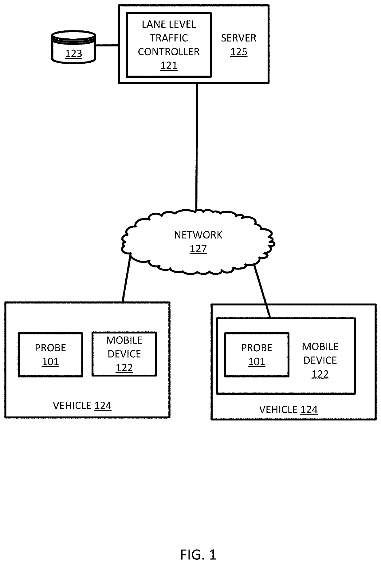
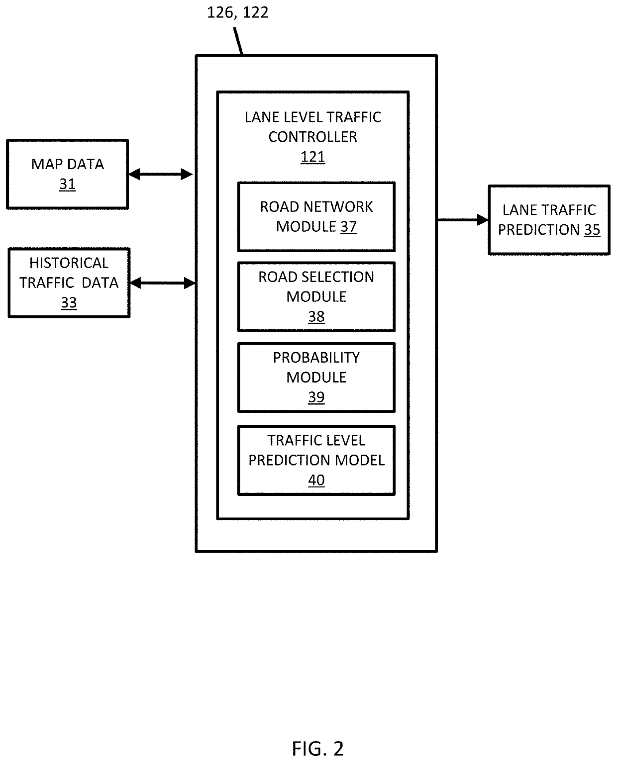
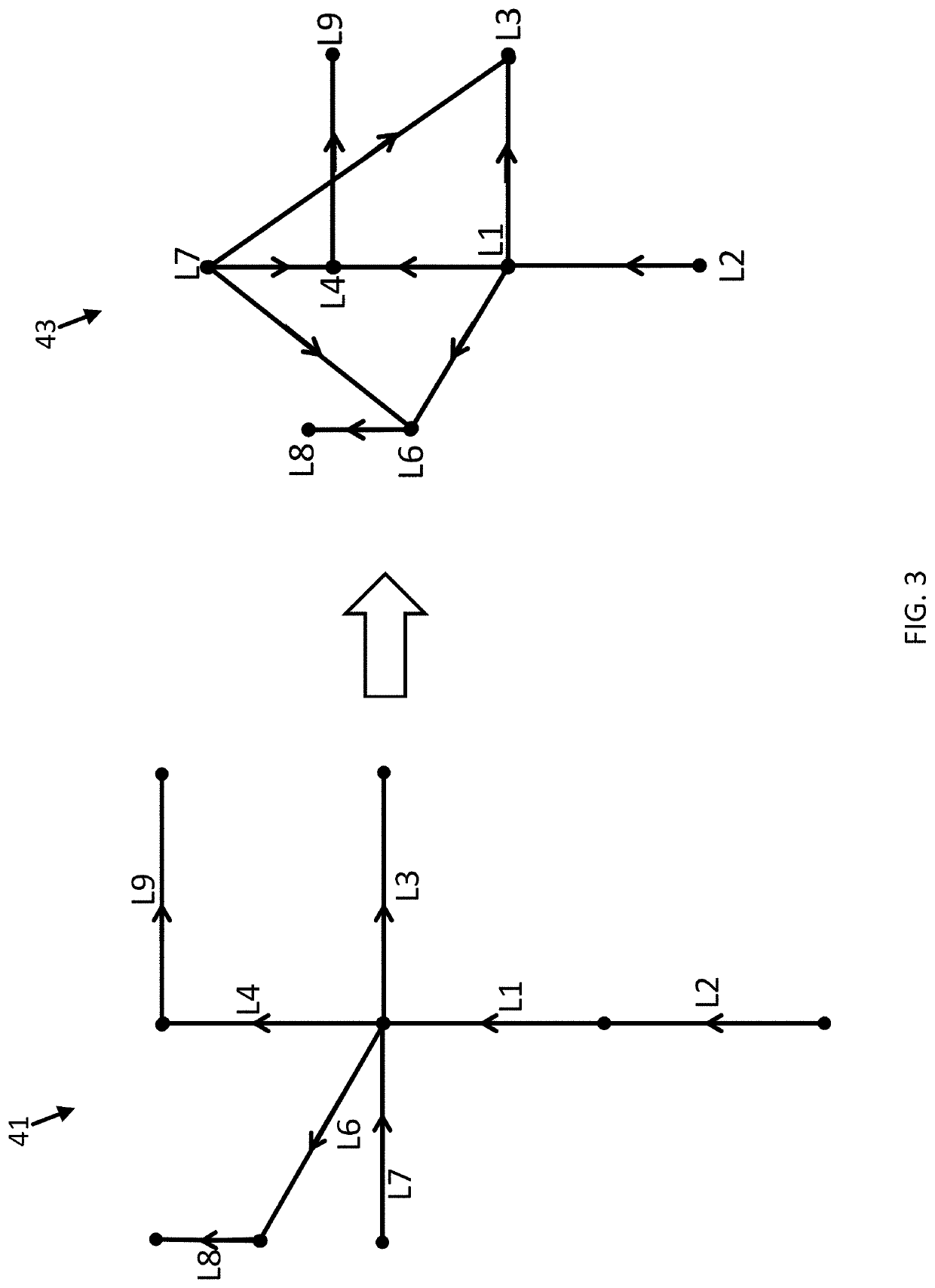
[0136]A method for predicting future traffic for a roadway, the method comprising:[0137]receiving road network data in a first road network format describing a road network including a plurality of road links and a plurality of intersections, wherein the first road network format includes graph edges for the plurality of road links and graph nodes for the plurality of intersections;[0138]converting the road network data to a second road network format describing the road network, wherein the second road network format includes graph edges for the plurality of intersections and graph nodes for the plurality of road links;[0139]selecting a road link from the plurality of road links;[0140]calculating a related link subset from the plurality of road links for the selected road link;[0141]querying historical data for the related link subset; and[0142]calculating a predicted traffic level for the selected road link in response to the historical data for the related link subset.

embodiment 2

[0143]The method of embodiment 1, further comprising:[0144]identifying a multi-lane road link including a plurality of lanes with at least one lane upstream of the selected road link, the at least one lane connected to the selected road link in the second road network format.

embodiment 3

[0145]The method of embodiment 1 or 2, further comprising:[0146]receiving position data from a mobile device; and[0147]matching the multi-lane road link to the position data.


PUM


Abstract

An apparatus and method for determining a traffic level in the future. A road network including graph edges for a plurality of intersections and graph nodes for a plurality of road links is identified. A road link of interest is selected from the plurality of road links. A set of related link subset are calculated for the selected road link. Historical data is queried for the related link subset. A predicted traffic level is calculated for the selected road link in response to the historical data for the related link subset.

Description

FIELD[0001]The following disclosure relates to traffic predictions, and more specifically, to traffic predictions at a lane level based on related road sections selected from a probabilistic graphic model.BACKGROUND[0002]Traffic reporting is the study of movement of vehicles on the roads. Analytical techniques may manage and track traffic information and derive travel times, guide driving behavior and optimize road infrastructure for cities. Traffic Message Channel (TMC) and other traffic services deliver traffic information to customers. Traffic incidents and traffic flow are reported through broadcasts. Traffic delays may be caused by one or more of congestion, construction, accidents, special events (e.g., concerts, sporting events, festivals), weather conditions (e.g., rain, snow, tornado), and so on.[0003]Traffic services typically provide a speed or a range of speeds (e.g., low, medium, high) for a particular road. Another characteristic, traffic volume measures the total thro...

Claims


Application Information

Patent Timeline
Patent Type & Authority Applications(United States)
IPC IPC(8): G08G1/01G08G1/052G06N5/04
CPCG08G1/052G08G1/012G08G1/0129G08G1/0133G06N5/046G08G1/0112G06N5/01G06N7/01
Inventor FOWE, JAMES
Owner HERE GLOBAL BV
Learn More