Assembly method for an air intake of a jet engine of an aircraft

a jet engine and air intake technology, applied in the direction of machines/engines, mechanical equipment, transportation and packaging, etc., can solve the problems of increased weight and considerable installation tim

Active Publication Date: 2020-08-20
AIRBUS OPERATIONS (SAS)
View PDF0 Cites 0 Cited by
  • Summary
  • Abstract
  • Description
  • Claims
  • Application Information

AI Technical Summary

Benefits of technology

[0007]The present invention has an object of proposing an assembly method for an air intake of a jet

Problems solved by technology

The lip consists of numerous elements which are attached to one another, resulting in considerable installation time a

Method used


Image

  • Assembly method for an air intake of a jet engine of an aircraft

Examples


Embodiment Construction

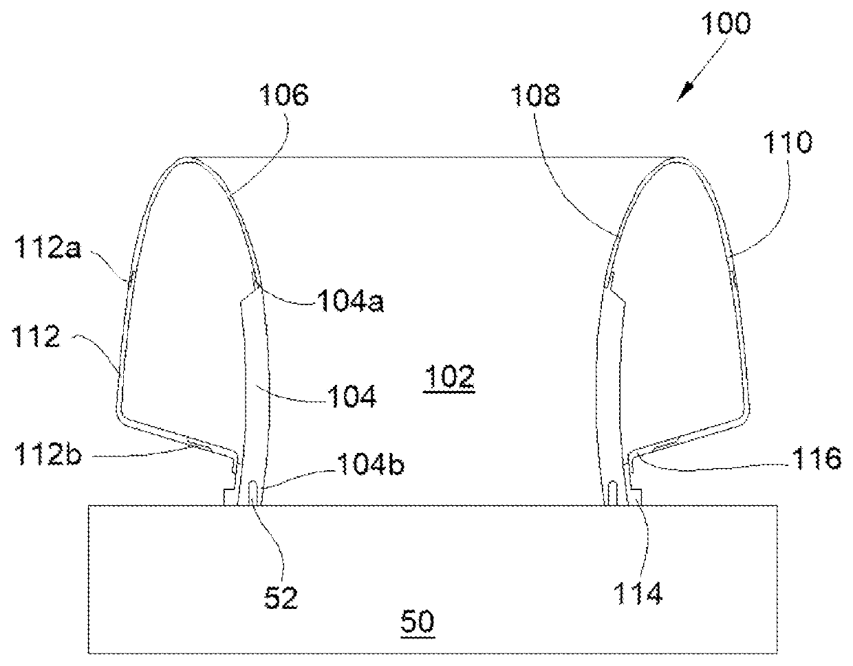
[0027]The FIGURE shows an air intake 100 of a jet engine of an aircraft. The air intake 100 is arranged on an assembly chassis 50 which serves to hold the air intake 100 as it is assembled.

[0028]The air intake 100 delimits a duct 102. The air intake 100 comprises an acoustic panel 104 which is positioned around the duct 102 and an outside panel 112 which is positioned around the acoustic panel 104 and constitutes the outside fairing of the air intake 100.

[0029]The acoustic panel 104 and the outside panel 112 each have a generally cylindrical shape.

[0030]The acoustic panel 104 has a front edge 104a which projects forwards and a rear edge 104b which projects rearwards.

[0031]The outside panel 112 has a front edge 112a which projects forwards and a rear edge 112b which projects rearwards.

[0032]The air intake 100 also comprises flanges 114 which are attached around and to the outside of the acoustic panel 104, at the rear edge 104b of the acoustic panel 104.

[0033]The air intake 100 also ...


PUM


Abstract

An assembly method for an air intake of a jet engine of an aircraft, comprising providing an acoustic panel, an outside panel, flanges and a collar, arranging a rear edge of the acoustic panel on an assembly chassis. The flanges and the collar are attached at the rear edge of the acoustic panel. A rear edge of the outside panel is attached to the attached collar. A first set of geometric data of a front edge of the acoustic panel is measured and a second set of geometric data of a front edge of the outside panel is measured. A U-shaped lip as a single element is produced based on the two sets of geometric data. An inside leg of the lip is attached to the front edge of the acoustic panel and an outside leg of the lip is attached to the front edge of the outside panel.

Description

CROSS-REFERENCES TO RELATED APPLICATIONS[0001]This application claims the benefit of the French patent application No. 1901560 filed on Feb. 15, 2019, the entire disclosures of which are incorporated herein by way of reference.FIELD OF THE INVENTION[0002]The present invention relates to an assembly method for an air intake of a jet engine of an aircraft, and to an air intake produced using such an assembly method.BACKGROUND OF THE INVENTION[0003]An air intake of a jet engine of an aircraft conventionally comprises a duct which is delimited by an acoustic panel which is positioned around the duct. The air intake also comprises a lip which constitutes the leading edge of the air intake and which extends the acoustic panel in the upstream direction, and an outside panel which constitutes the outside fairing of the air intake and which extends the lip on the outside.[0004]The air intake also comprises a flange which is attached to the outside of the acoustic panel and a collar which is ...

Claims


Application Information

Patent Timeline
IPC IPC(8): B64F5/10B64D33/02F02C7/045B33Y80/00
CPCB64F5/10B64D33/02F02C7/045B33Y80/00F05D2230/60B64D2033/0206B64D2033/0273F05D2230/31
Inventor LAURENT, JEAN-NOËL
Owner AIRBUS OPERATIONS (SAS)
Why Eureka
Try Eureka