Time-of-flight camera and proximity detector

a proximity detector and camera technology, applied in the field of time-of-flight (tof) imaging, can solve the problems of occupying space and apertures on the interior and exterior of the phono, speakers and microphones,

Active Publication Date: 2020-08-20
ANALOG DEVICES INT UNLTD
View PDF0 Cites 9 Cited by
  • Summary
  • Abstract
  • Description
  • Claims
  • Application Information

AI Technical Summary

Benefits of technology

[0020]This overview is intended to provide an overview of subject matter of the present patent application. Further limitations and disadvantages of conventional and traditional approaches will become apparent to one of skill in the art, through comparison of such systems with some aspects of the present invention as set forth in the remainder of the present application with reference to the drawings.

Problems solved by technology

Having multiple cameras and detectors, in addition to speakers and microphones, consumes space and apertures on the interior and exterior of the phone

Method used


Image

  • Time-of-flight camera and proximity detector
  • Time-of-flight camera and proximity detector
  • Time-of-flight camera and proximity detector

Examples


example 9

[0111 provides a system according to one or more of the preceding examples, where the first mode is a low resolution mode.

[0112]Example 10 provides a system according to one or more of the preceding examples, where the first subset of the plurality of pixels includes less than about a quarter of the plurality of pixels.

[0113]Example 11 provides a system according to one or more of the preceding examples, where the first subset of the plurality of pixels includes adjacent pixels.

[0114]Example 12 provides a system according to one or more of the preceding examples, where the first subset of the plurality of pixels includes non-adjacent pixels.

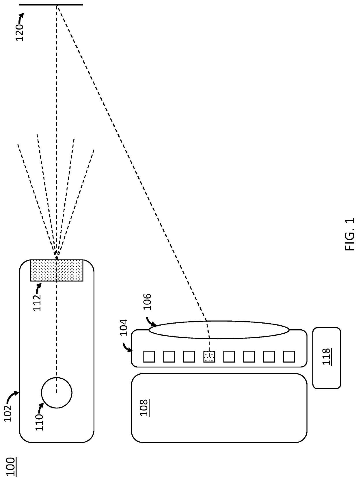
[0115]Example 13 provides a system according to one or more of the preceding examples, where in a second mode, the plurality of pixels including the second subset of the plurality of pixels are activated, and the processor generates a high resolution depth image.

[0116]Example 14 provides a system according to one or more of the preceding examples...


PUM


Abstract

Time of Flight (ToF) image processing systems and methods for proximity detection are disclosed. In particular, use of a separate proximity detector can be eliminated by using the time of flight image processing system as disclosed herein. In particular, the time of flight image processing system has two modes: a low resolution proximity detection mode and a high resolution imaging mode.

Description

RELATED APPLICATIONS[0001]This application claims priority to U.S. Patent Application Ser. No. 62 / 806,595 filed Feb. 15, 2019 entitled “Time-of-Flight Camera and Proximity Detector”, U.S. Patent Application Ser. No. 62 / 806,561 filed Feb. 15, 2019 entitled “Spatial Correlation Sampling in Time-of-Flight Imaging”, and U.S. Patent Application Ser. No. 62 / 806,722 filed Feb. 15, 2019 entitled “Depth Non-Linearity Compensation in Time-of-Flight Imaging”, which are hereby incorporated by reference in their entirety. Additionally, this application is related to U.S. Patent Application entitled “Spatial Correlation Sampling in Time-of-Flight Imaging” filed Jan. 14, 2020, and U.S. Patent Application entitled “Depth Non-Linearity Compensation in Time-of-Flight Imaging” filed Jan. 14, 2020, which are hereby incorporated by reference in their entirety.FIELD OF THE DISCLOSURE[0002]The present disclosure pertains to time of flight (ToF) imaging. More specifically, this disclosure describes systems...

Claims


Application Information

Patent Timeline
Patent Type & Authority Applications(United States)
IPC IPC(8): G01S17/894G01S17/10G01S17/32H04N5/225H04N5/232G01S7/4863G01S7/4913G01S7/4915
CPCH04N5/2256G01S17/894G01S17/10G01S17/32H04N5/23245H04N13/271H04N13/254H04N13/128G01S7/4915G01S17/36G01S7/4913H04N2013/0081G01S7/4863H04N23/56H04N23/667
Inventor LE DORTZ, NICOLASHURWITZ, JONATHAN EPHRAIM DAVIDBARNES, ERIK D.
Owner ANALOG DEVICES INT UNLTD
Why Eureka
Try Eureka