Coaxial nozzle design for laser cladding/welding process

a technology of laser cladding/welding process and coaxial nozzle, which is applied in the direction of welding apparatus, metal-working equipment, manufacturing tools, etc., can solve the problems of inconvenient use, easy burning of nozzles, and inconvenient us

Inactive Publication Date: 2005-03-17
HONEYWELL INT INC
View PDF47 Cites 113 Cited by
  • Summary
  • Abstract
  • Description
  • Claims
  • Application Information

AI Technical Summary

Benefits of technology

[0019] In view of the foregoing disadvantages, the present invention provides a laser powder fusion welding nozzle wherein the nozzle can be used for a longer period of time in welding processes and the like. In particular, a new laser powder fusion welding nozzle is provided that does not require the replacement of nozzle inserts, does not as frequently sustain nozzle tip deformation, and provides more reliably-symmetric powder flow, overcoming several of the disadvantages present in the prior art by combining many novel features in order to achieve a new laser powder fusion welding nozzle design.
[0020] Knowledge and experience in the field of laser cladding / welding process has led to the present design. Compared with prior nozzles, the present nozzle design has the following advantageous features: it is easy to clean inside the nozzle; it provides better shielding during laser welding; it eliminates the use of nozzle inserts; the powder stream interacts with laser beam outside the nozzle; it is easy to adjust the laser focus distance in order to get different laser spot sizes; and it is easy to adjust the positioning of cone-shaped powder stream with respect to the center of laser beam.
[0021] Because nozzle inserts are not used in the present nozzle design, the nozzle does not need replacement and beam alignment that would arise from use of such inserts. The new nozzle design has many advantages (mentioned above) over prior nozzles which are believed to enable nozzle performance that is significantly advanced.

Problems solved by technology

However, there have been some drawbacks in certain elements in LPF welding systems, including the nozzle that serves to bring together both the laser light that performs the welding as well as the powder which is used to construct the weld.
For example, nozzle inserts used in some nozzles may easily burn, may take an undue amount of time to replace the inserts or to align the beam, and / or the overall function is not consistent.
Such nozzles are generally not suited for many applications.
For some prior nozzles, the bottom edge of the inner insert is so thin or sharp that it may not tolerate heat reflected from the welding zone.
Therefore, the inner insert may be damaged during the laser welding process.
This may be especially noticeable when welding on an inclined surface where severe laser beam reflection occurs.
It can take a few hours or more to replace such nozzle inserts which can be costly.
In some cases, the inner insert sustains only minor damage.
Such damage can also reduce the powder utilization efficiency, since less powder may flow to the welding zone.
This can lead to two possible results, both of which are unacceptable: the weld is hot and material buildup is less, and / or cracking is created inside the weld.
Because such prior nozzles' performance are not consistent, delays in production may occur that increase production time by days.
During the laser welding process, molten particles or plasma fumes may seal the micropores and make the nozzle's function inconsistent and unreliable.
In view of the several disadvantages present in current laser nozzles, additional costs and time are spent in order to accommodate the frequent failures that arise when such prior laser nozzles are actually used in welding processes.

Method used


Image

  • Coaxial nozzle design for laser cladding/welding process
  • Coaxial nozzle design for laser cladding/welding process
  • Coaxial nozzle design for laser cladding/welding process

Examples


Embodiment Construction

)

[0040] The detailed description set forth below in connection with the appended drawings is intended as a description of presently-preferred embodiments of the invention and does not represent the only forms in which the present invention may be constructed and / or utilized. The description sets forth the functions and the sequence of steps for constructing and operating the invention in connection with the illustrated embodiments. However, it is to be understood that the same or equivalent functions and sequences may be accomplished by different embodiments that are also intended to be encompassed within the spirit and scope of the invention.

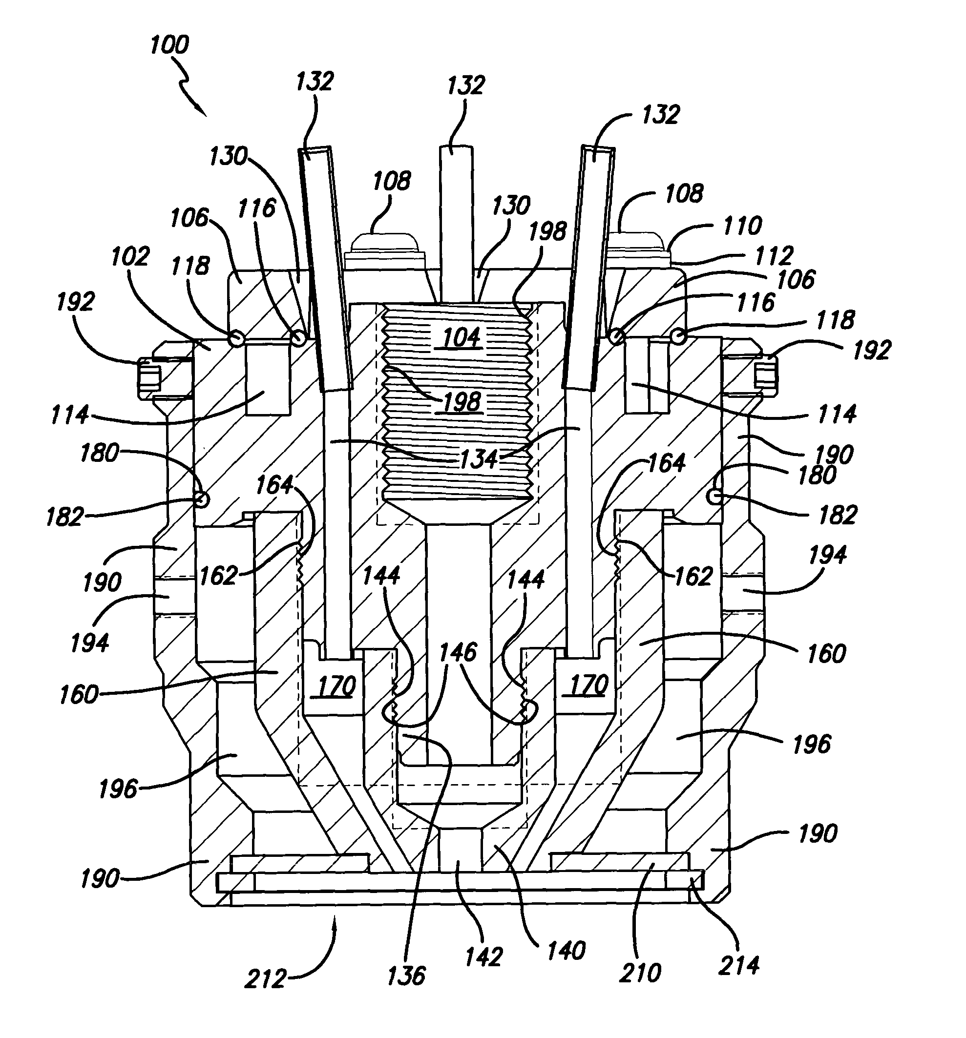
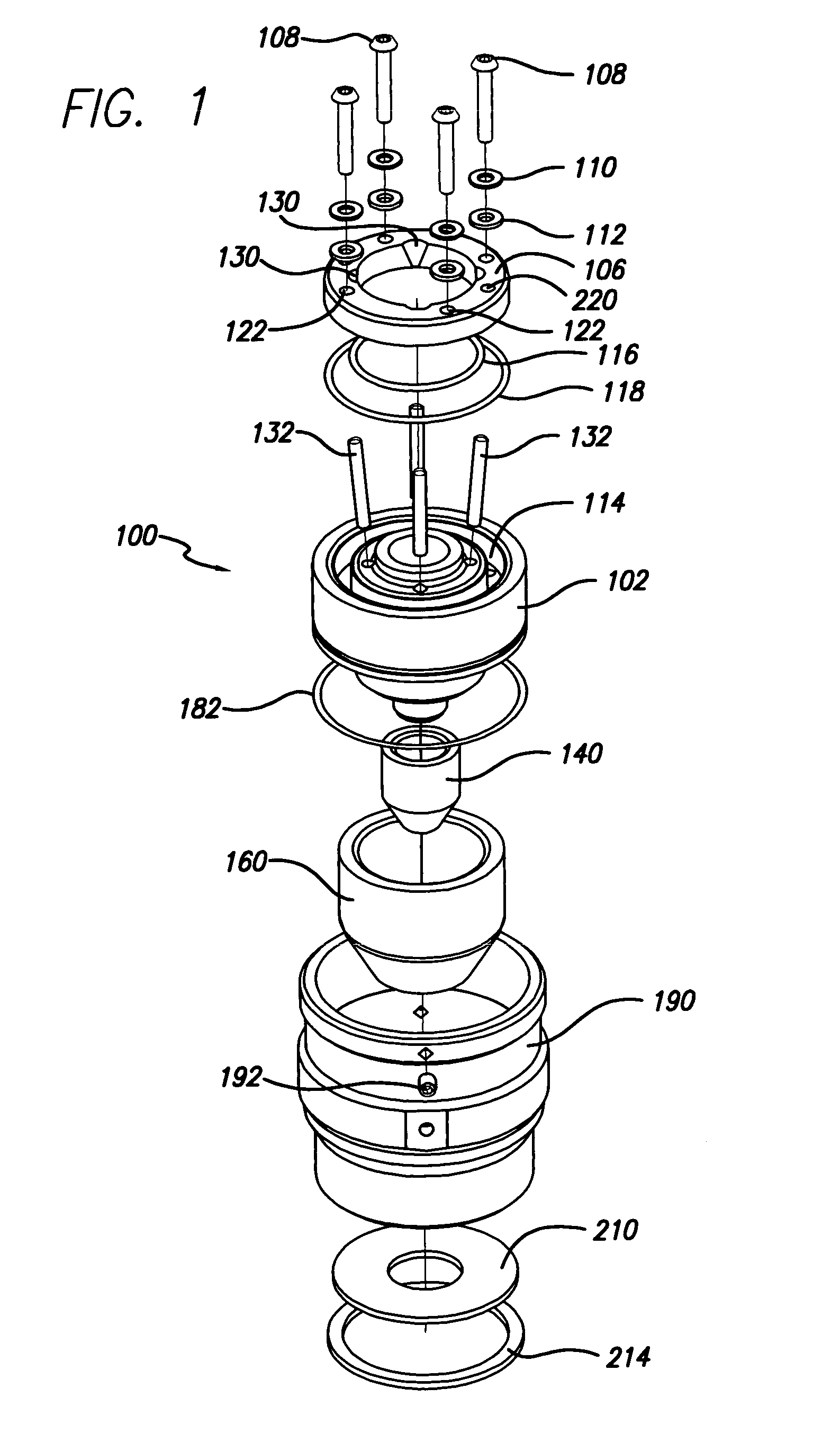
[0041] As best shown in FIGS. 1 and 4, the coaxial laser powder fusion (LPF) welding nozzle 100 has a main body 102 which generally serves as a core element and helps to receive and guide both the powder used for laser fusion (not shown) as well as having a central channel 104 through which the laser light passes. The main body 102 is capped o...


PUM

PropertyMeasurementUnit
areaaaaaaaaaaa
volumeaaaaaaaaaa
compositionaaaaaaaaaa

Abstract

A laser nozzle for use in a laser powder fusion (LPF) welding process provides longer service life and ease of maintenance. Eliminating the use of laser nozzle inserts, the laser nozzle uses an inner tip that is less subject to damage from the welding process. The laser beam travels down an open central passage to exit out the inner tip in focused alignment with a conical powder flow stream ending in a point generally coincident with the laser beam. The powder supply travels through a passage that is generally coaxial to the central laser passage. A circumscribing passage for inert shielding gas or the like is coincidentally coaxial with both the laser powder flow channel and the central laser channel. Coolant is circulated through a main body portion of the nozzle in order to keep the entire assembly cool. Both the laser and the flow of powder may be adjusted according to operating preferences. A porous shielding cover prevents ejecta and other materials from entering into the shielding gas flow channel. The entire assembly is easily constructed from readily available materials and is easily disassembled for cleaning. Reassembly is also easily achieved in order to enable rapid refurbishment and reconstitution of an optimal LPF welding nozzle.

Description

CROSS-REFERENCES TO RELATED APPLICATIONS [0001] This patent application incorporates by reference, but claims no priority to the following patents and regular and provisional patent applications: [0002] U.S. patent application Ser. No. 10 / 071,025 filed Feb. 8, 2002 for Hand Held Laser Powder Fusion Welding Torch; and [0003] U.S. patent application Ser. No. 10 / 206,411 filed Jul. 26, 2002 for Powder Feed Splitter for Hand-Held Laser Powder Fusion Welding Torch.COPYRIGHT AUTHORIZATION [0004] Portions of the disclosure of this patent document may contain material which is subject to copyright and / or mask work protection. The copyright and / or mask work owner has no objection to the facsimile reproduction by anyone of the patent document or the patent disclosure, as it appears in the Patent and Trademark Office patent file or records, but otherwise reserves all copyright and / or mask work rights whatsoever. BACKGROUND OF THE INVENTION [0005] 1. Field of the Invention [0006] This invention ...

Claims


Application Information

Patent Timeline
Patent Type & Authority Applications(United States)
IPC IPC(8): B23K26/14
CPCB23K26/1411B23K26/144
Inventor HU, YIPING
Owner HONEYWELL INT INC
Why Eureka
Try Eureka