Read-Through Metal Tag and Methods of Making and Using the Same

Inactive Publication Date: 2020-08-20
ENSURGE MICROPOWER ASA
View PDF0 Cites 0 Cited by
  • Summary
  • Abstract
  • Description
  • Claims
  • Application Information

AI Technical Summary

Benefits of technology

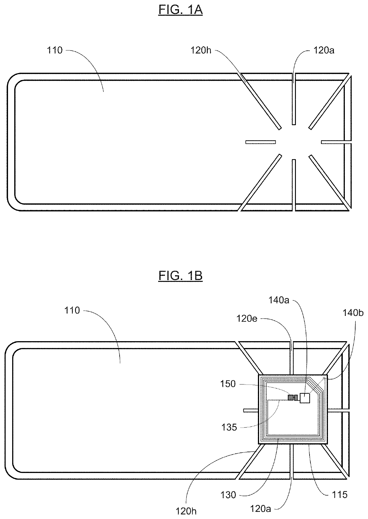
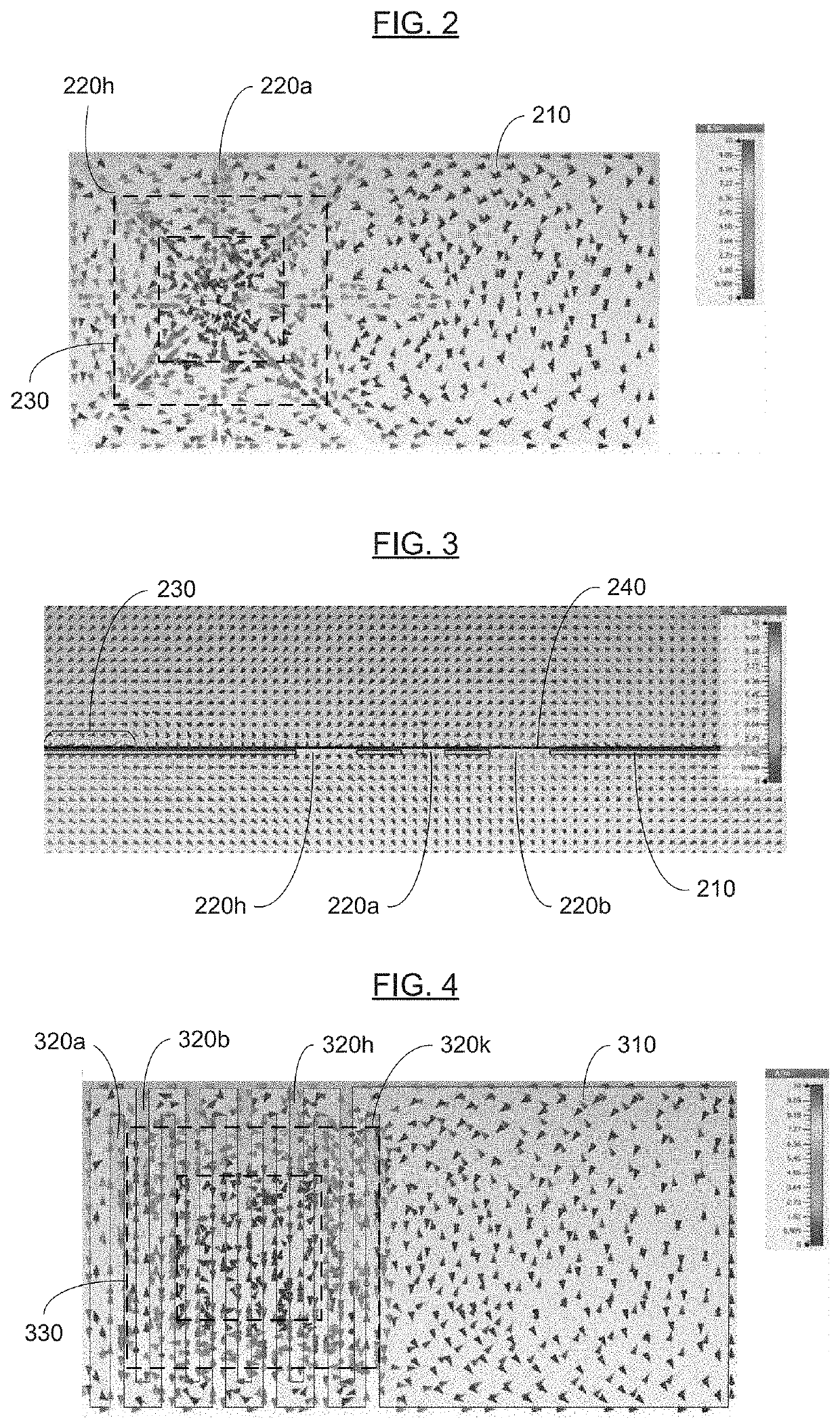
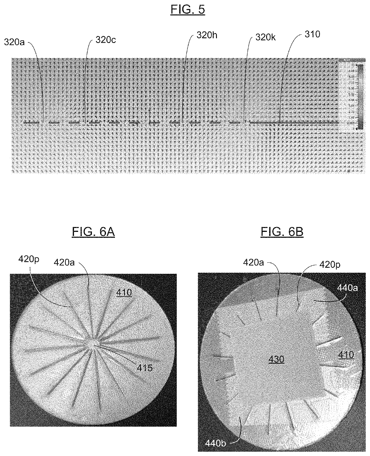
This patent describes a method of improving the performance of wireless antennas on metal substrates by creating cuts or slits in the metal to prevent electromagnetic currents (eddy currents) from affecting the performance of the antenna. By doing so, the wireless communication device becomes more readable and the read range of the wireless tag is not significantly affected. The method also involves forming openings in the metal substrate through which the antenna overlaps, which further enhances the readability and reduces the magnitude of electromagnetically-induced currents. This invention facilitates the use of metal substrates for wireless communication devices and improves their read range.

Problems solved by technology

Wireless communication tags typically cannot be encapsulated with or be in close-proximity to a metal sheet or foil (e.g., aluminum or steel), since eddy currents in the metal prevent RF communication with the antenna.
The magnetic field emanating from the metal sheet or foil opposes the magnetic field from the antenna (e.g., according to Lenz's law), thus compromising the performance of the antenna by decreasing magnetic flux and increasing the resonant frequency of the antenna.
However, this solution is not economically viable due to precision design rules for and stringent manufacturing tolerances of such spiral antennas.
However, such a material may be too expensive to produce and / or use on a mass scale.

Method used


Image

  • Read-Through Metal Tag and Methods of Making and Using the Same
  • Read-Through Metal Tag and Methods of Making and Using the Same
  • Read-Through Metal Tag and Methods of Making and Using the Same

Examples


Embodiment Construction

[0035]Reference will now be made in detail to various embodiments of the invention, examples of which are illustrated in the accompanying drawings. While the invention will be described in conjunction with the following embodiments, it will be understood that the descriptions are not intended to limit the invention to these embodiments. On the contrary, the invention is intended to cover alternatives, modifications and equivalents that may be included within the spirit and scope of the invention as defined by the appended claims. Furthermore, in the following detailed description, numerous specific details are set forth in order to provide a thorough understanding of the present invention. However, it will be readily apparent to one skilled in the art that the present invention may be practiced without these specific details. In other instances, well-known methods, procedures, components, and circuits have not been described in detail so as not to unnecessarily obscure aspects of th...


PUM


Abstract

Embodiments of the disclosure pertain to a wireless communication device and a method of reading a wireless communication device in which the magnitude of electromagnetically-induced currents in a metal-containing substrate is reduced. The metal-containing substrate has one or more openings therethrough. The device includes an antenna configured to (i) receive one or more first wireless signals from a reader and (ii) transmit or broadcast one or more second wireless signals and an integrated circuit coupled to the antenna. The antenna overlaps with at least one of the one or more openings.

Description

RELATED APPLICATION(S)[0001]The present application claims priority to U.S. Provisional Pat. Appl. No. 62 / 806,287, filed Feb. 15, 2019 (Atty. Docket No. IDR5120-PR), incorporated herein by reference in its entirety.FIELD OF THE INVENTION[0002]The present invention generally relates to the field(s) of wireless communication, identification and / or security devices (e.g., wireless communication tags, such as radio-frequency identification [RFID] tags, electronic article surveillance [EAS] tags, and near-field communication [NFC] tags). More specifically, embodiments of the present invention pertain to a wireless communication device including an antenna and a metal structure, such as a metal foil or blanket-deposited metal layer. The metal structure includes cuts or slits configured to reduce the effect of eddy currents in the metal structure on the magnetic flux of signals transmitted and received by the antenna.DISCUSSION OF THE BACKGROUND[0003]Wireless communication tags, such as RF...

Claims


Application Information

Patent Timeline
IPC IPC(8): H01Q1/52H04W4/80H01Q1/22
CPCH04W4/80H01Q1/528H01Q1/2216H01F2038/143H01F2027/348H04B5/77
Inventor MUKHERJEE, SOMNATHHAGEL, OLLE JONNY
Owner ENSURGE MICROPOWER ASA
Why Eureka
Try Eureka