

Printed circuit board assembly
- Summary
- Abstract
- Description
- Claims
- Application Information
AI Technical Summary
Benefits of technology
Problems solved by technology
Method used
Image

Examples
Embodiment Construction
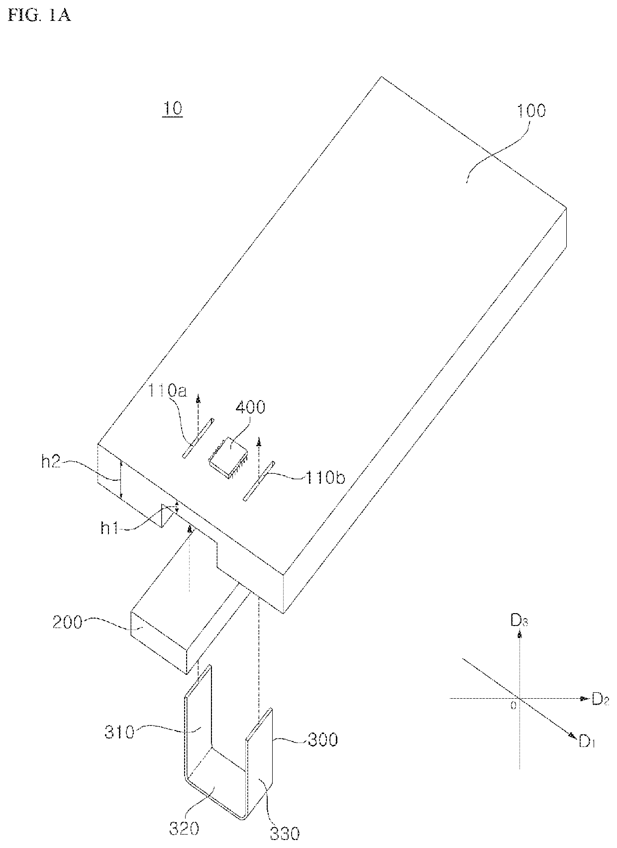
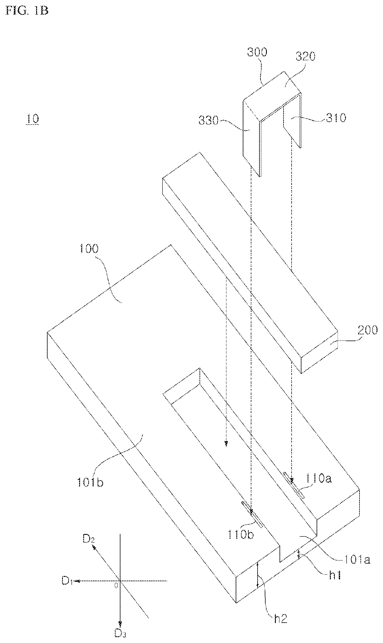
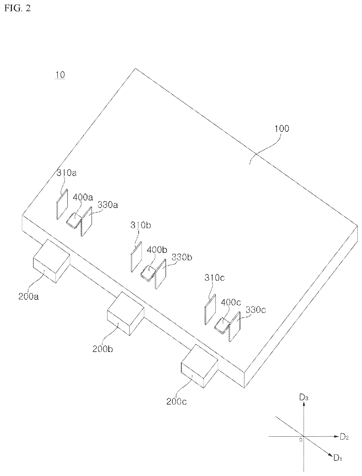
[0037]Hereinafter, the present disclosure will be described in detail with reference to the accompanying drawings. For the purpose of clear and brief description of the present disclosure, illustrations of parts irrelevant to the description will be omitted. The same reference numbers will be used throughout this specification to refer to the same or similar components.
[0038]Suffixes such as “module” and “unit”, which are used in the following description, may be used to refer to elements or components for easy preparation of the specification, and the suffixes do not have any special meaning or function. Accordingly, the suffixes such as “module” and “unit” may be used in an interchangeable manner.
[0039]Terms such as “includes” or “has” used herein should be considered to indicate the presence of several features, numbers, steps, operations, elements, components or combinations thereof disclosed in the specification, but it should be understood that one or more other features, numb...
PUM
 Abstract
Description
Claims
Application Information