Voltage detection circuit

Active Publication Date: 2012-06-14
NUVOTON
View PDF1 Cites 3 Cited by
  • Summary
  • Abstract
  • Description
  • Claims
  • Application Information

AI Technical Summary

Benefits of technology

[0053]In another aspect, the voltage detection circuit with an auto-trimming mode of the present disclosure may utilize a comparator circuit for calibrating the detection error. In the auto-trimming mode, it may find out a

Problems solved by technology

Especially when there are tons of data computing procedures paralleled on a center process unit of the system, lacking of a stable operating voltage / current may cause a system crash.
For example, when the battery module of a mobile phone is running out of electricity, a voltage level provided by the battery module is reduced gradually, such that other components of the mobile phone may not receive sufficient power supply.
An undershooting of the voltage level on the power supply is viewed as a typical unstable condition.

Method used


Image

  • Voltage detection circuit
  • Voltage detection circuit
  • Voltage detection circuit

Examples


Embodiment Construction

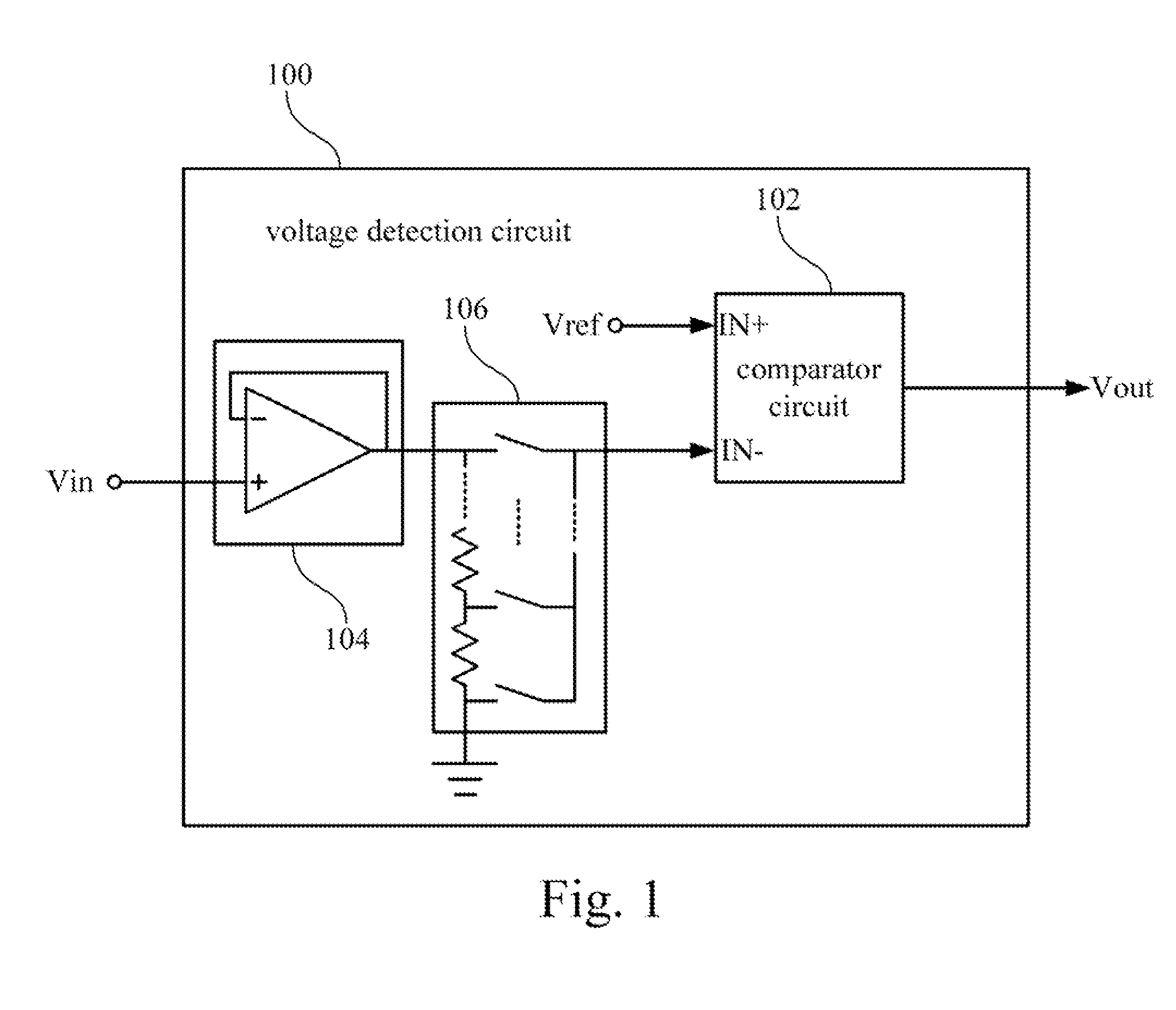
[0021]Please refer to FIG. 1, which is a function block diagram illustrating a voltage detection circuit 100.

[0022]As shown in FIG. 1, the voltage detection circuit 100 includes a comparator circuit 102. Two input terminals (input terminal IN+, input terminal IN−) of the comparator circuit 102 are coupled to a signal under test Vin (the signal to be detected) and a reference signal Vref (the signal served as a reference standard of comparison in the voltage detection of the present disclosure) respectively. The comparator circuit 102 can be used for comparing voltage levels of the input terminal IN+ and the input terminal IN−, so as to generate the comparison outcome (i.e. the output signal Vout) after the comparison.

[0023]In practical applications, the input terminal IN− of the comparator circuit 102 may not be directly connected to the signal under test Vin. In the embodiment of FIG. 1, the voltage detection circuit 100 further includes a unity-gain operational amplifier 104 and a...


PUM


Abstract

A voltage detection circuit including a comparator circuit, a tunable gain circuit and a switch circuit is disclosed. The comparator circuit has a first input terminal and a second input terminal. The tunable gain circuit is coupled between the first input terminal and a reference signal. The tunable gain circuit has a plurality of gain configurations. The tunable gain circuit adjusts the reference signal and transmits the adjusted reference signal to the first input terminal. The switch circuit selectively transmits a signal under test or the reference signal to the second input terminal. When the voltage detection circuit is in an auto-trimming mode, the switch circuit transmits the reference signal to the second input terminal and the tunable gain circuit sequentially adopts the gain configurations until the comparator circuit detects that voltage levels of the first input terminal and the second input terminal are substantially equal.

Description

RELATED APPLICATIONS[0001]This application claims priority to Taiwan Application Serial Number 099143786, filed Dec. 14, 2010, which is herein incorporated by reference.BACKGROUND[0002]1. Field of Invention[0003]The present disclosure relates to a circuit. More particularly, the present disclosure relates to a detection circuit.[0004]2. Description of Related Art[0005]With the rocketing development of Consumer Electronics, desktop computers, laptop computers, mobile phones, personal digital assistants or portable players are widespread in daily life of modern society. These electronic products may satisfy the demands for telecommunication, data storage, entertainment, productivity, social networking or information achieving of users. In order to operate these electronic product smoothly, a stable power supply is a basic requirement. In general, a desktop computer utilizes a fixed power supply module. On the other hand, a portable electronic product (e.g. mobile phone) may include a ...

Claims


Application Information

Patent Timeline
IPC IPC(8): H03F3/45
CPCH03F3/45475H03F2200/471H03F2200/78H03F2203/45522H03F2203/45618H03F2203/45591H03F2203/45594H03F2203/45616H03F2203/45528
Inventor LI, WEN-YI
Owner NUVOTON
Why Eureka
Try Eureka