Eureka AIR delivers breakthrough ideas for toughest innovation challenges, trusted by R&D personnel around the world.

Impulse line-clogging detecting unit and impulse line-clogging detecting method

Active Publication Date: 2008-08-28
YOKOGAWA ELECTRIC CORP
View PDF3 Cites 3 Cited by
  • Summary
  • Abstract
  • Description
  • Claims
  • Application Information

AI Technical Summary

Benefits of technology

[0018]According to the present invention, by obtaining the correction value for suppressing change of the variance ratio, which is caused by change of a flow rate of fluid, and correcting the variance ratio wing using correction value, it is possible to detect the state of clogging of the impulse lines precisely without being affected by the flow rate of the fluid.

Problems solved by technology

If the impulse lines are clogged in such a differential pressure transmitter, it is difficult to measure the differential pressure precisely.
That is, since it is require to change a threshold value or a setting value of the standard fluctuation variance Vas depending on the flow rate, a work load of an operator increases, and apparatus costs increase when the change of the setting value is automated.

Method used


Image

  • Impulse line-clogging detecting unit and impulse line-clogging detecting method
  • Impulse line-clogging detecting unit and impulse line-clogging detecting method
  • Impulse line-clogging detecting unit and impulse line-clogging detecting method

Examples


first embodiment

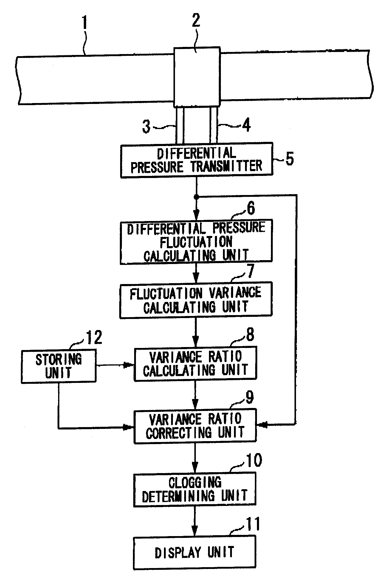
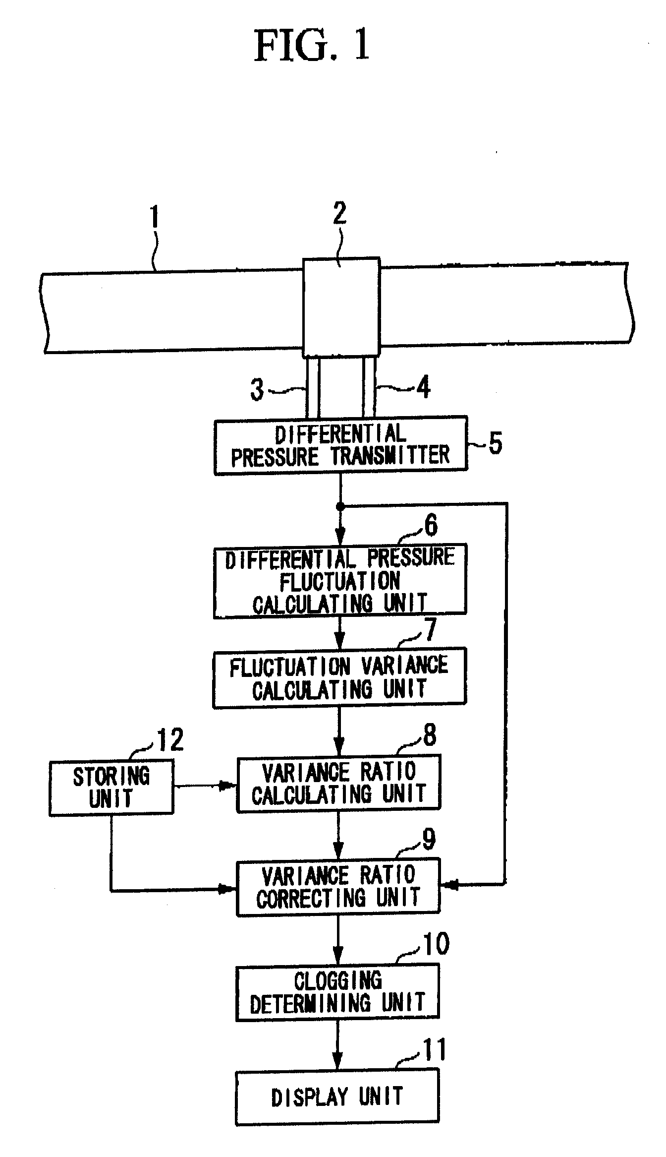
[0024]FIG. 1 is a schematic view showing a configuration of an impulse line-clogging detecting according to a first embodiment of the present invention. This impulse line-clogging detect apparatus detects clogging of a high pressure side impulse line 3 and a low pressure side impulse line 4, which are respectively arranged at a front stage (high pressure side) and a rear stage (low pressure side) of an orifice 2 provided in a fluid pipe 1 of a plant or the like.

[0025]As shown in FIG. 1, the impulse line-clogging detecting apparatus includes a differential pressure transmitter (differential pressure detecting unit) 5, a differential pressure fluctuation calculating unit 6, a fluctuation variance calculating unit 7, a variance ratio calculating unit 9, a variance ratio correcting unit 9, a clogging determining unit 10, a display unit 11, and a storing unit 12.

[0026]The differential pressure transmitter 5 detects a differential pressure of fluid based on high pressure transmitted via t...

second embodiment

[0043]A construction of an impulse line-clogging detecting apparatus of the second embodiment has the same elements as those of the impulse line-clogging detecting apparatus of the first embodiment shown in FIG. 1, except that the differential pressure transmitter 5 has an additional function which will be described below, and therefore, explanation of the same elements will be omitted. For the sake of convenience of description, a differential pressure transmitter of the second embodiment is denoted by reference numeral 5a to distinguish from the differential pressure transmitter 5 of the first embodiment.

[0044]The differential pressure transmitter 5a in the impulse line-clogging detecting apparatus of the second embodiment detects a differential pressure of fluid based on a high pressure transmitted via the high pressure side impulse line 3 and a low pressure transmitted via the low pressure side impulse line 4, compares the detected differential pressure with predetermined thresh...


PUM


Abstract

This impulse line-clogging detecting apparatus is provide with: a differential pressure detecting unit that detects a differential pressure of a fluid, and outputs time series data of the differential pressure; a differential pressure fluctuation calculating unit that calculates a differential pressure fluctuation; a fluctuation variance calculating unit that calculates a variance of the differential pressure fluctuation; a variance ratio calculating unit that calculates a variance ratio of the differential pressure fluctuation variance calculated by the fluctuation variance calculating unit to a differential pressure fluctuation variance obtained in advance in a normal state of the high and low pressure side impulse lines; a variance ratio correcting unit that calculates a correction value for suppressing change of the variance ratio; and a clogging determining unit that determines whether the high and low pressure side impulse lines are clogged, based on the variance ratio corrected by the variance ratio correcting unit.

Description

[0001]Priority is claimed on Japanese Patent Application No. 20074-45294, filed Feb. 26, 2007, the contents of which at incorporated herein by reference.BACKGROUND OF THE INVENTION[0002]1. Field of the Invention[0003]The present invention relates to an impulse line-clogging detecting apparatus and an impulse line-clogging detecting method for detecting clogging of impulse lines in a differential pressure transmitter for measuring a differential pressure of fluid flowing through a piping.[0004]2. Description of Related Art[0005]As is generally known in the related art, a differential pressure transmitter measures a differential pressure between a front stage (high pressure side) and a rear stage (low pressure side) of an orifice provided in a pipe in which fluid flows, based on a pressure transmitted through impulse lines arranged at the front and rear stages of the orifice. If the impulse lines are clogged in such a differential pressure transmitter, it is difficult to measure the d...

Claims


Application Information

Patent Timeline
IPC IPC(8): G01F1/50
CPCG01F1/50
Inventor HASHIZUME, TAKUMIWAKUI, TETSUYAEINO, JYUN-ICHIMIYAJI, NOBUOYUKI, YOSHITAKA
Owner YOKOGAWA ELECTRIC CORP
Why Eureka
Eureka Blog
Learn More