Processing system

Active Publication Date: 2012-06-28
KLEO HALBLEITERTECHNIK GMBH & CO KG
View PDF1 Cites 1 Cited by
  • Summary
  • Abstract
  • Description
  • Claims
  • Application Information

AI Technical Summary

Benefits of technology

[0010]The advantage of the solution according to the invention is to be seen in the fact that with this solution it is possible in a simple manner to detect the position of the object edges on the object carrier exactly and, therefore, to align the structures generated on the object exactly relative to the object edges.
[0060]In this respect, it is particularly favorable when the light sources illuminating the diffuser are arranged in a base member bearing the object carrier plate, are, in particular, integrated in this base member so that, as a result, no additional attachments on the object carrier are required.

Problems solved by technology

The problem with such processing systems is that when the plate-like objects are intended to be placed on the object carrier or processed on both sides, in particular exposed, the object has to be positioned on the object carrier in a defined manner each time.

Method used


Image

  • Processing system
  • Processing system
  • Processing system

Examples


first embodiment

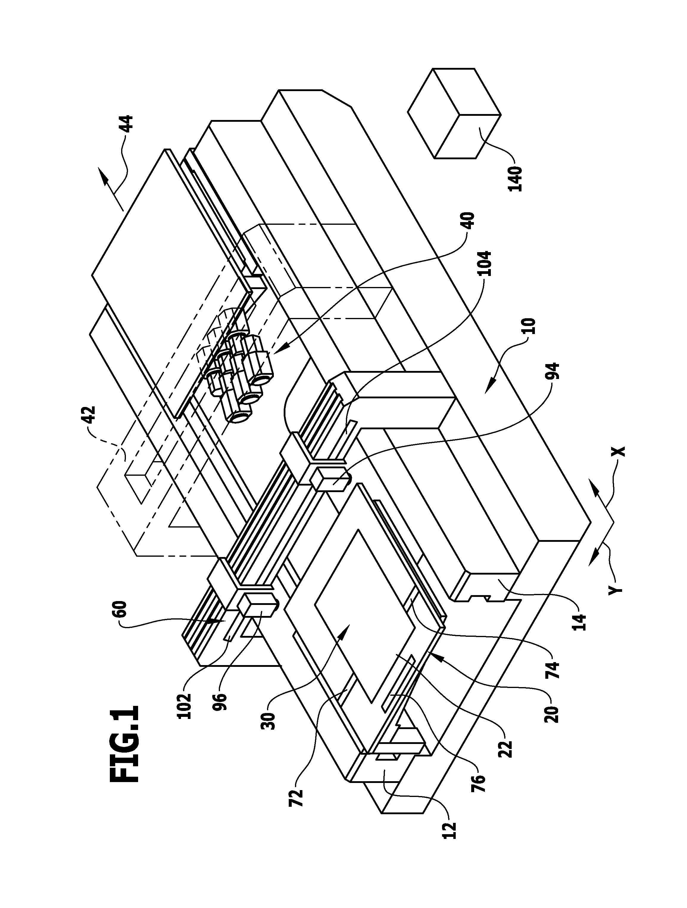
[0080]an exposure device according to the invention, illustrated in FIG. 1, comprises a machine frame which is designated as a whole as 10 and has two longitudinal guides 12, 14 which are arranged at a distance from one another and on which an object carrier designated as a whole as 20 is guided for movement in a first direction designated, for example, as X direction.

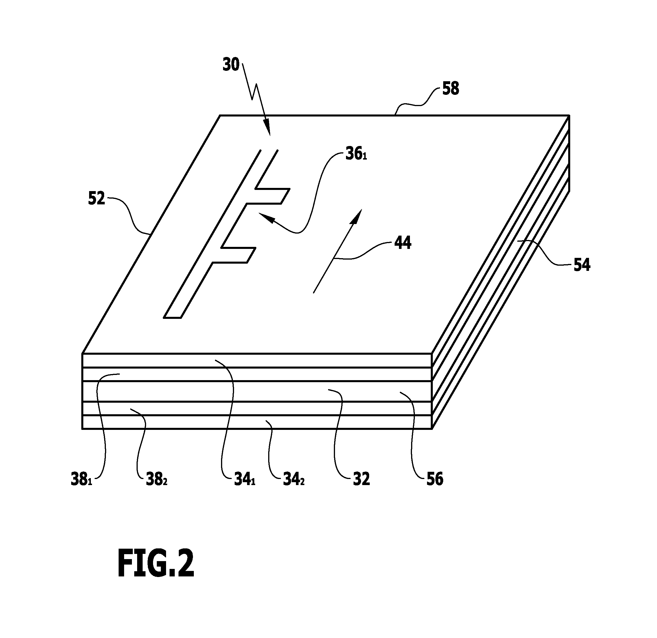
[0081]The object carrier 20 has an object carrier surface 22, on which objects 30 can be placed which comprise, for example, as illustrated in FIG. 2, a substrate 32 which is coated on both sides with photosensitive layers 341 and 342, wherein structures 36 can be generated in the photosensitive layers 341 and 342 by way of photochemical conversion of the respective photosensitive layer 34.

[0082]These structures 36 are, for example, structures which cover a copper layer 381 and 382 on the substrate 32 and so the copper layer 381 and 382 on the substrate 32 can be removed, for example, subsequently within the scope of a...

second embodiment

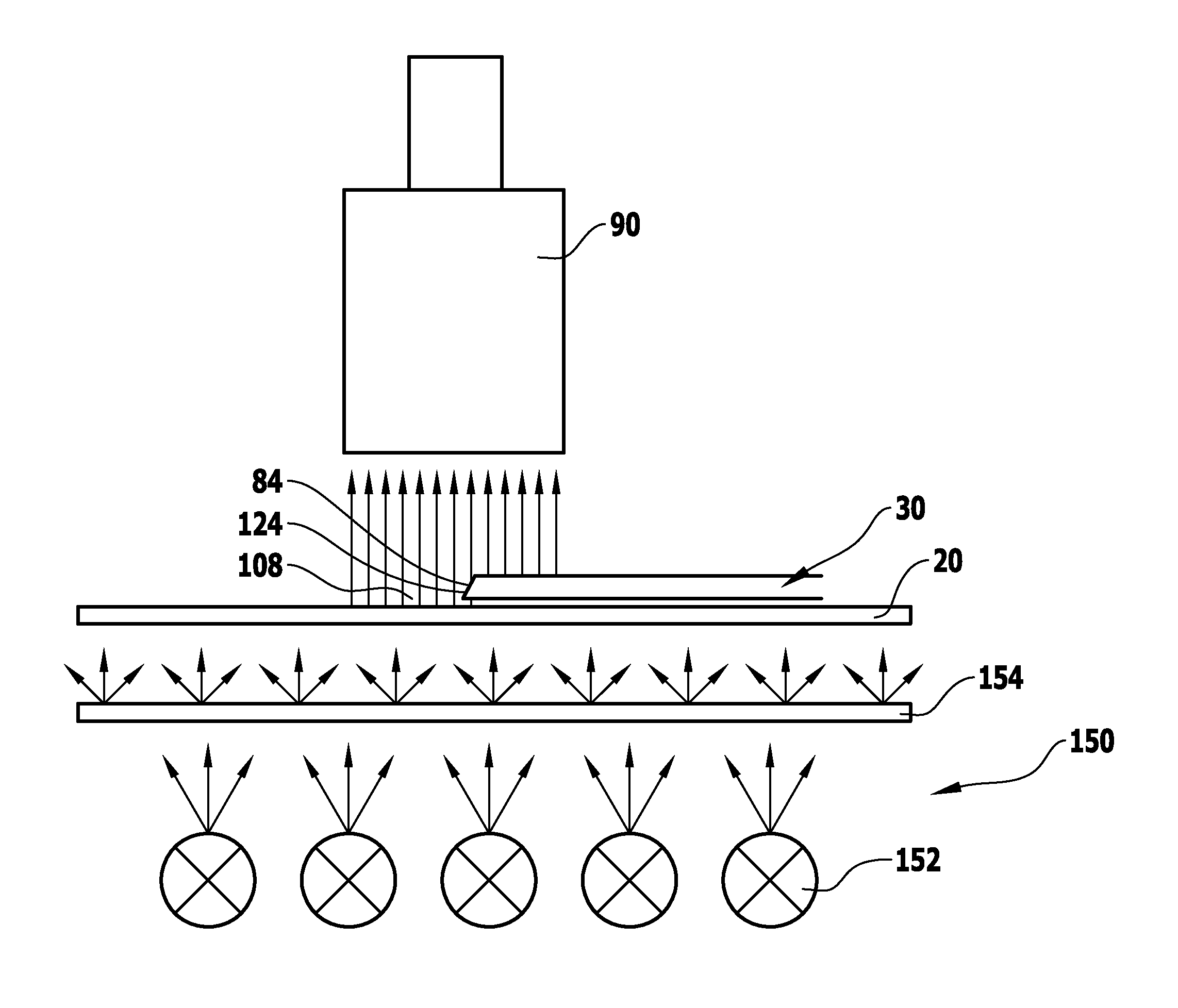
[0119]In a processing system according to the invention, the respective edge illumination unit 150 is, as illustrated in FIG. 11, integrated into the object carrier 20, wherein the object carrier 20 comprises a base member 162 and an object carrier plate 164 resting on the base member 162, wherein the object carrier plate 164 is designed, for example, as a ceramic plate which, for its part, forms the object carrier surface 22 on its side facing away from the base member 162.

[0120]The edge illumination unit 150 is, for example, integrated into the base member 162 such that the diffuser 154 is formed by the object carrier plate 164, which therefore acts, for its part, as an optical diffuser, and is seated on the base member 162 and has light directed onto it by the light sources 152 designed as light diodes from its side facing away from the object carrier surface 22, wherein the light sources 152 are formed, for example, by two or more rows of light diodes seated next to one another....

third embodiment

[0124]As for the rest, the third embodiment operates in the same way as the preceding embodiments and so reference is made in full to the preceding embodiments with respect to the remaining features.


PUM


Abstract

A processing system for plate-like objects is provided, with an exposure device and an object carrier with an object carrier surface for receiving the object. The exposure device and the carrier are movable relative to one another, such that the exact position of the object relative to the carrier is determinable. An edge detection device is provided which comprises at least one edge illumination unit having an illumination area, within which an object edge located in the respective object edge area has light directed onto it from the side of the carrier. At least one edge image detection unit is provided on a side of the object located opposite the carrier, the edge image detection unit imaging an edge section of the object edges located in the illumination area as an edge image, such that the respective edge image is detectable in its exact position relative to the carrier.

Description

[0001]This application is a continuation of International application number PCT / EP2010 / 059284 filed on Jun. 30, 2010.[0002]This patent application claims the benefit of International application No. PCT / EP2010 / 059284 of Jun. 30, 2010 and German application No. 10 2009 032 210.8 of Jul. 3, 2009, the teachings and disclosure of which are hereby incorporated in their entirety by reference thereto.BACKGROUND OF THE INVENTION[0003]The invention relates to a processing system for plate-like objects, in particular an exposure system for plate-like objects, comprising an exposure device and an object carrier with an object carrier surface for receiving the object, wherein the exposure device and the object carrier are movable relative to one another for the purpose of exposing the object.[0004]Processing systems of this type are known.[0005]Such a processing system could be used, for example, for the laser treatment of plate-like objects.[0006]It is, however, also conceivable to use such a...

Claims


Application Information

Patent Timeline
IPC IPC(8): G06K9/46
CPCG03F9/00G03F7/70791
Inventor OPOWER, HANSJUENGER, KLAUS
Owner KLEO HALBLEITERTECHNIK GMBH & CO KG
Why Eureka
Try Eureka