Shifting device

Active Publication Date: 2007-11-13
KK TOKAI RIKA DENKI SEISAKUSHO
View PDF17 Cites 27 Cited by
  • Summary
  • Abstract
  • Description
  • Claims
  • Application Information

AI Technical Summary

Benefits of technology

[0008]Accordingly, it is an objective of the present invention to provide a shifting device that improves the reliability of detection of the position of a shift lever.

Problems solved by technology

However, if the shifting device is used for an extended period, the contact electrode 59 and the contacts 52 to 59 deteriorate with time due to wear.
Therefore, the method using this shifting device has low reliability as a method for detecting the position of the shift lever.

Method used


Image

  • Shifting device
  • Shifting device
  • Shifting device

Examples


Embodiment Construction

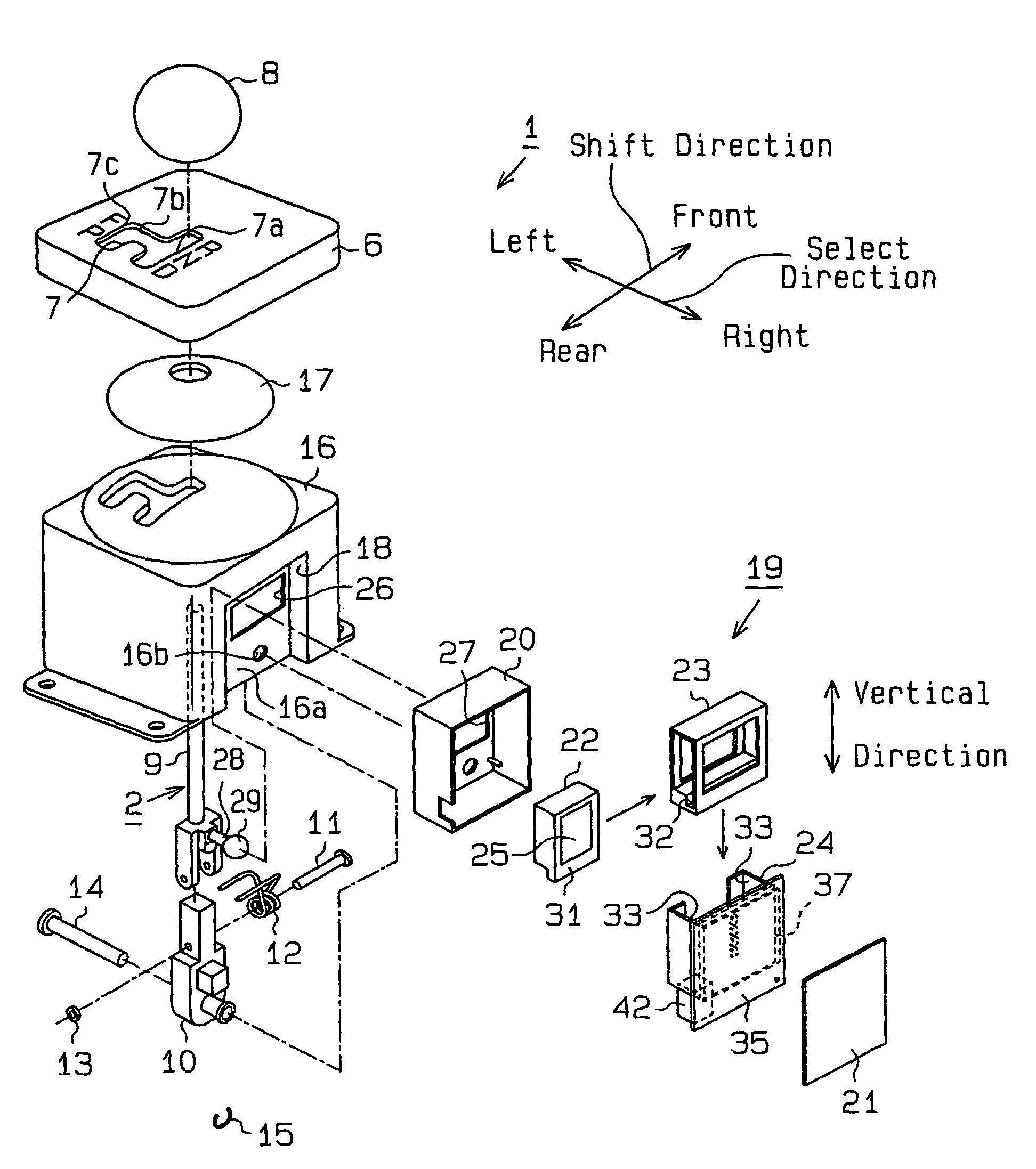
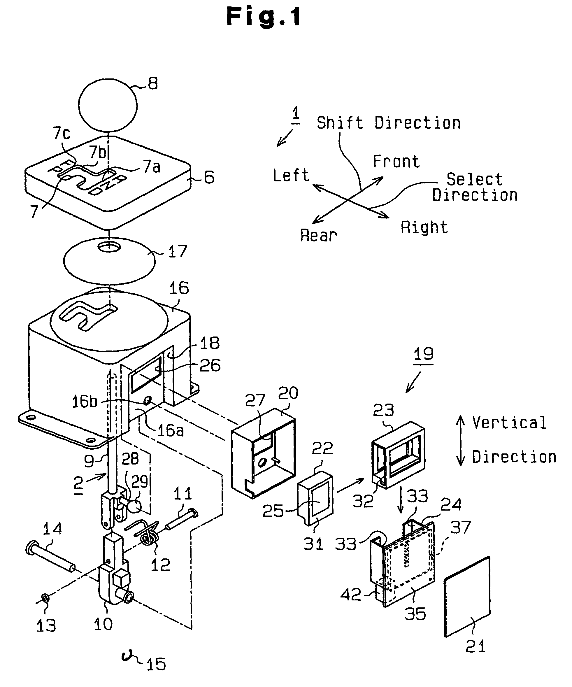
[0025]A shifting device 1 according to a first embodiment of the present invention will now be described with reference to FIGS. 1 to 7. The front, the rear, the left, and the right of the shifting device 1 are defined as shown in FIGS. 1 and 2 in this embodiment.

[0026]As shown in FIG. 1, the shift lever 2 includes the knob 8, a lever main body 9, and a retainer 10. The lever main body 9 is pivotally coupled to the retainer 10 with a pin 11. Thus, the shift lever 2 is supported by the retainer 10 to be pivotable leftward and rightward about the pin 11. The torsion spring 12 is engaged with a shaft of the pin 11. The torsion spring 12 urges the shift lever 2 toward the F position when the shift lever 2 is in the first gate 7a. A nut 13 is threaded to the distal portion of the pin 11 to prevent the pin 11 from falling off.

[0027]A shaft 14 extends through a lower portion of the pin 11. The shaft 14 extends in a direction perpendicular to the direction of the pin 11. The shaft 14 is sup...


PUM


Abstract

A shifting device includes a housing, a shift lever, and a sensor unit. The shift lever is moved along frontward or rearward and leftward or rightward to select one of shift positions. The sensor unit is of a non-contact type and detects the selected shift position. The sensor unit includes a plurality of sensors and a magnet. The relative positions of the sensors and the magnet are variable. The sensor unit detects the selected shift position according to the relative positions. According to movement of the shift lever, at least one of the group of the sensors and the magnet is moved along a first movement axis and a second movement axis. The first and second movement axes extend in different directions.

Description

BACKGROUND OF THE INVENTION[0001]The present invention relates to a shifting device for changing a shift position.[0002]A typical vehicle having an automatic transmission has a floor shifting device. A shifting device has a shift lever for switching the gear position of the automatic transmission. Some shifting devices provide manual gear selection as well as automatic gear selection. Such a shifting device typically has a several gates formed in a panel. For example, such a shifting device has a first gate for automatic gear selection, a second gate for manual gear selection, and a third gate for switching between the automatic and manual gear selections.[0003]In the automatic gear selection, a driver moves the shift lever to the first gate and shifts the shift lever to one of a P (parking) position, an R (reverse) position, an N (neutral) position, and a D (advance) position. Accordingly, the gear position of the automatic transmission is changed. In the manual gear selection, the...

Claims


Application Information

Patent Timeline
IPC IPC(8): B60K17/12B60K17/04G01B21/00B60K20/00F16H59/02F16H59/10
CPCF16H59/105F16H59/0204Y10T74/20201Y10T74/20159Y10T74/20085Y10T74/20018Y10T74/20067Y10T74/2003
Inventor MATSUI, KAZUHITOTANIGUCHI, MASAHIROSHOJI, OSAMUSUZUKI, NORIYUKI
Owner KK TOKAI RIKA DENKI SEISAKUSHO
Why Eureka
Try Eureka