Apparatus for DC motor position detection with capacitive ripple current extraction

Inactive Publication Date: 2006-06-20
VISTEON GLOBAL TECH INC
View PDF41 Cites 705 Cited by
  • Summary
  • Abstract
  • Description
  • Claims
  • Application Information

AI Technical Summary

Benefits of technology

[0010]In satisfying the above need, as well as, overcoming the enumerated drawbacks and other limitations of the related art, the present invention provides an improved position detection system for a DC motor.
[0012]The system provides a low cost option for obtaining the motor position information that does not require a special H-bridge, motor, or additional power supplies, by simply inserting a capacitive impedance element in parallel with the motor terminal.
[0013]The system provides a position sensing system that does not add excessive additional voltage drops and power losses by using capacitive sensing element in parallel with the main motor circuit such that main DC power does not go though the sensing circuit.
[0014]The system provides a position sensing system that will have a high useful signal to sensed signal ratio for high signal sensitivity and accuracy, which is inherently provided by the capacitor ripple currents.
[0015]The system provides a position sensing system that will not have pulse gaining problem due to brush bounces or pulse missing problem during startup, regenerative braking, or stop modes of operations, by inserting the sensing circuits directly across the motor terminals such that commutation events of the motor will not be missed by the sensing circuit.

Problems solved by technology

The use of a position sensor increases the cost, size and weight of the system, and reduces the reliability and environmental compatibility of the system.
This position sensing technique, however, is known to have poor position accuracy, is sensitive to environmental conditions such as temperatures, has poor durability due to the mechanical contact between the wiper and the resistive trace, and has high system cost due to additional wiring required between the motor and the controller.
Though the technique disclosed in U.S. Pat. No. 5,798,624 resolved several problems associated with the designs that use position sensors or potentiometers as mentioned above, it still suffers drawbacks.
Further, the system would require two sensors for bi-directional operations thereby increasing the cost of the system.
If the sensor is located in the battery return, the system cannot capture commutation pulses in braking mode.
In addition, the system has poor useful signal sensitivity / accuracy since the entire motor current including the main DC component is embedded in the sensor signal.
The system may have pulse missing problems during start-up and stop coasting due to the use of a fixed band pass filter on the motor current signal.
Further, the system may gain pulses due to brush bounces.
Furthermore, since the main motor current goes through the current sensor, the system will have excessive voltage drops or power losses associated with the sensor.
However, it still suffers significant drawbacks.
The cost of the system is high due to the need for two current sources in the signal conditioning circuit and the need for a charge pump.
Also, the system only works with MOSFET based H-bridge modules, not with bipolar transistors.
The system may have pulse missing problems during motor start-up and stop due to the use of fixed-value high pass filters, and may have pulse gaining problems due to brush bounces.
Furthermore, the captured signal may vary among production motors of the same design and over the life span of the same motor due to the use of current pulses associated with delayed commutation.
The system cannot use MOSFET-based H-bridges, otherwise it will miss pulses during the braking mode.
Furthermore, since the main motor current has to go through the sensing inductor, excessive voltage drops or power losses will be present if a small inductor is used.

Method used


Image

  • Apparatus for DC motor position detection with capacitive ripple current extraction
  • Apparatus for DC motor position detection with capacitive ripple current extraction
  • Apparatus for DC motor position detection with capacitive ripple current extraction

Examples


Embodiment Construction

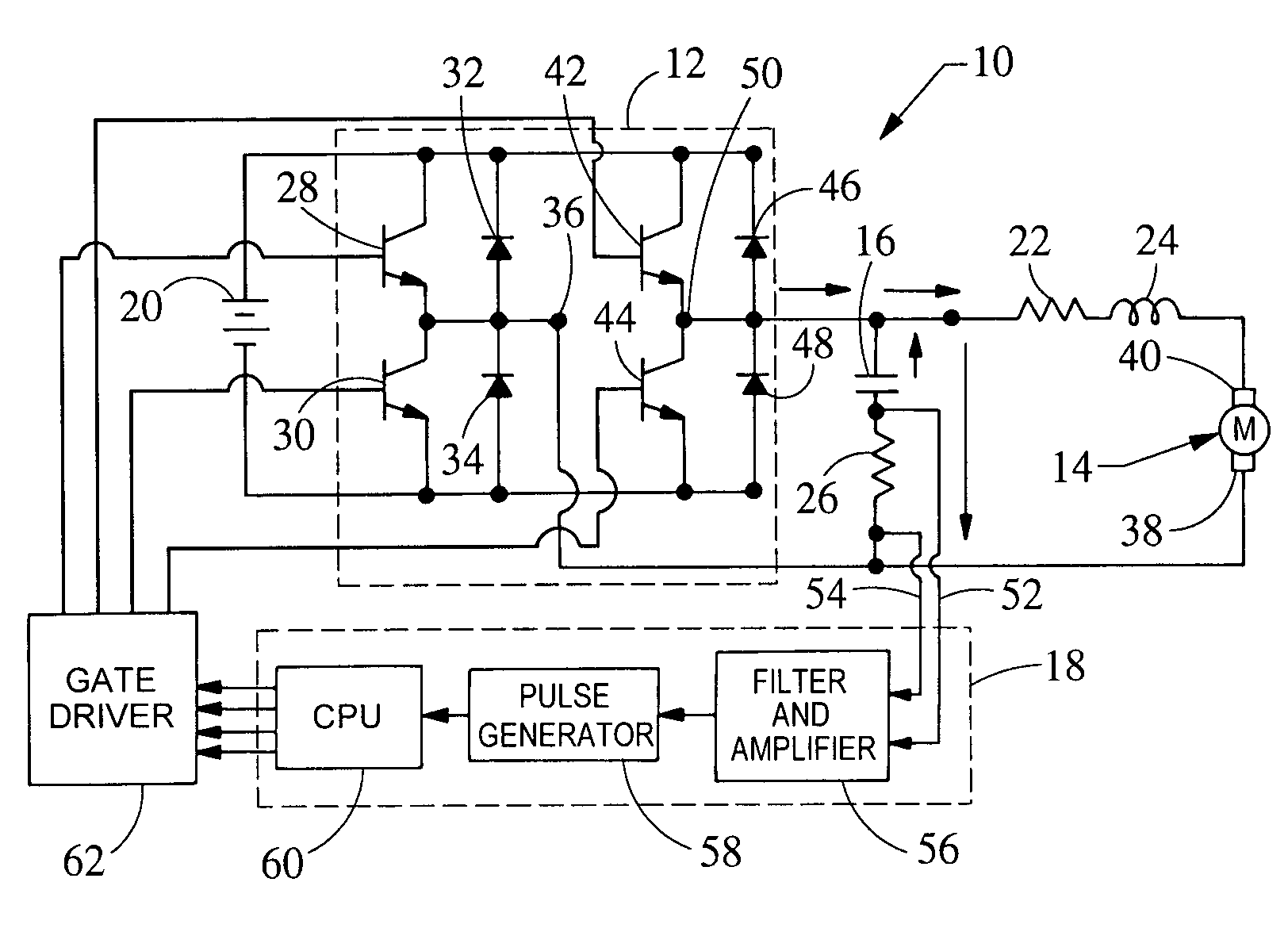
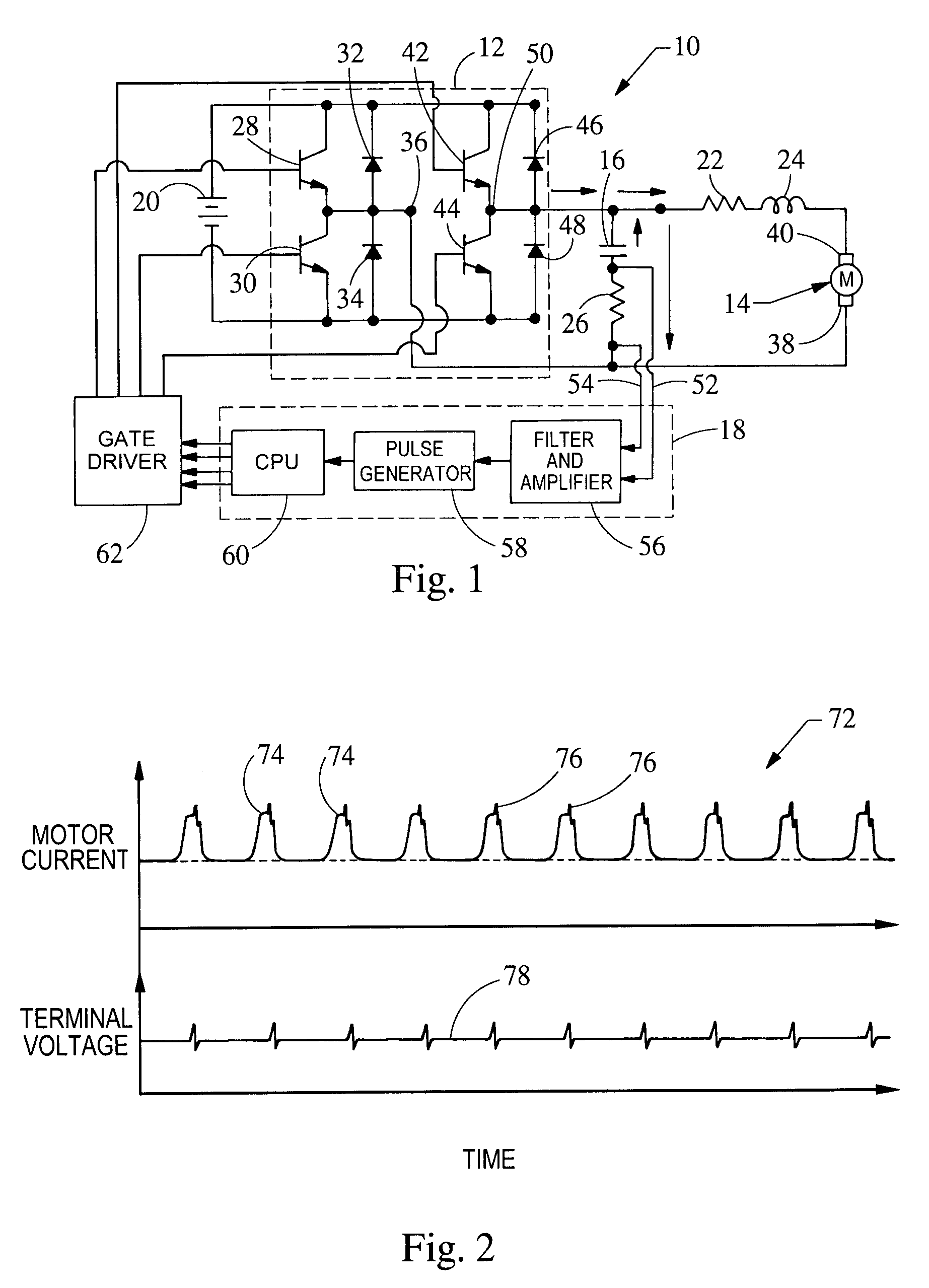
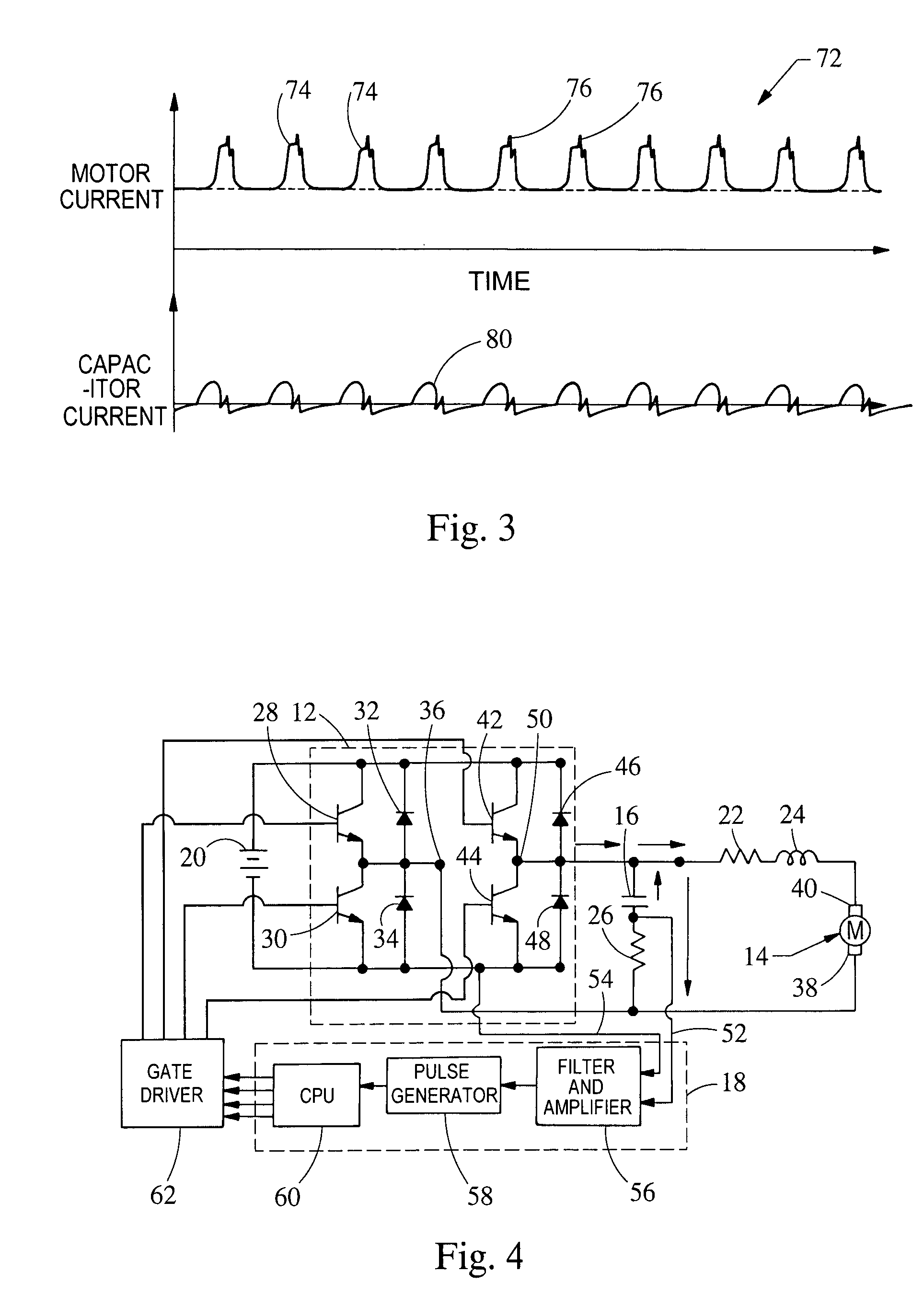
[0024]Referring now to FIG. 1, a system embodying the principles of the present invention is illustrated therein and designated at 10. The system 10 includes a power electronics switching circuit 12, a DC motor 14, a capacitor 16, and a ripple current detection apparatus 18. A power source 20, shown as an automotive battery, provides power to the switching circuit 12. The switching circuit 12 is shown as an H-bridge switching circuit, the details of which will be discussed further below. The switching circuit provides voltage to drive the motor 14. Resistor 22 and inductor 24 represent the effective resistance and inductance of the DC motor 14, respectively. A combination of capacitor 16 and impedance 26 is in electrical parallel connection with the motor 14 and the switching circuit 12. Further, an impedance 26 is connected in electrical series with the capacitor 16 across the motor 14. A first node 52 of the current ripple detection apparatus 18 is connected between the capacitor ...


PUM


Abstract

An apparatus for determining angular positions of DC motor includes a capacitor connected in parallel with the DC motor. The current flowing through the capacitor, at any given time, is an AC ripple current responsive to a commutation event of the DC motor. The capacitor partially sources the motor current ripples during commutation and recharges itself during the off-commutation period. Since the number of commutation events per mechanical revolution is pre-determined once the DC motor is designed, the frequency of the AC ripple currents through the capacitor corresponds to the frequency of commutation, and thus a motor position of the DC motor.

Description

BACKGROUND[0001]1. Field of the Invention[0002]The present invention relates to position detection and control system for a Direct Current (DC) motor.[0003]2. Description of Related Art[0004]Often position control of a DC motor requires feedback about the position of the motor shaft. Typically, a position sensor, such as an optical or Hall Effect encoder, or resolver is used to obtain the motor shaft position. The use of a position sensor increases the cost, size and weight of the system, and reduces the reliability and environmental compatibility of the system. For applications where the output speed of the motor is rather low, such as an actuator that consists of a DC motor and a reduction gear mechanism, a potentiometer is also commonly used to sense the position of the output shaft. This position sensing technique, however, is known to have poor position accuracy, is sensitive to environmental conditions such as temperatures, has poor durability due to the mechanical contact bet...

Claims


Application Information

Patent Timeline
IPC IPC(8): H01R39/46
CPCH02P7/2805H02P7/0094
Inventor FU, ZHENXINGYOCKEY, KARIENNE A.AIELLO, FRANK J.WINKELMAN, JAMES R.HAAS, FRANK J.
Owner VISTEON GLOBAL TECH INC
Why Eureka
Try Eureka