Recording apparatus and correction method

a technology of recording apparatus and correction method, which is applied in the direction of spacing mechanism, printing mechanism, printing, etc., can solve the problem that the recording position of dots cannot be appropriately corrected

Active Publication Date: 2020-08-27
OKI ELECTRIC IND CO LTD
View PDF0 Cites 1 Cited by
  • Summary
  • Abstract
  • Description
  • Claims
  • Application Information

AI Technical Summary

Problems solved by technology

However, in the conventional method, for example, when a recording medium having multiple regions having different light reflection characteristics, such as a recording medium on which a regular pattern is formed or a recording medium having

Method used


Image

  • Recording apparatus and correction method
  • Recording apparatus and correction method
  • Recording apparatus and correction method

Examples


first embodiment

1. First Embodiment

1-1. Configuration of Main Part of Inkjet Printer

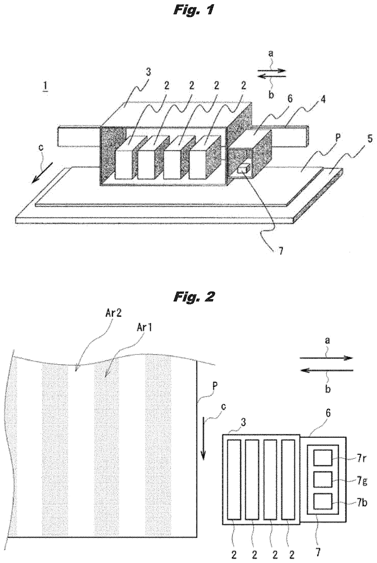
[0033]FIG. 1 illustrates a configuration of a main part of an inkjet printer 1 (or recording apparatus) according to a first embodiment. The inkjet printer 1 has a carriage 3 holding multiple (for example, four) inkjet type recording heads 2, a rail 4 extending in a main scanning direction indicated by arrows a and b, and a platen 5 arranged along the rail 4.

[0034]The carriage 3 moves back and forth in the main scanning direction along the rail 4. The four inkjet type recording heads 2 held by the carriage 3 respectively correspond to, for example, four ink colors of cyan, magenta, yellow, and black, and are arranged side by side in the main scanning direction. The inkjet type recording heads 2 each have, for example, multiple nozzles arranged in the main scanning direction indicated by “arrows a” and “arrow b” and a sub-scanning direction indicated by an arrow c, and ink is discharged from each of the nozzles. In t...

second embodiment

2. Second Embodiment

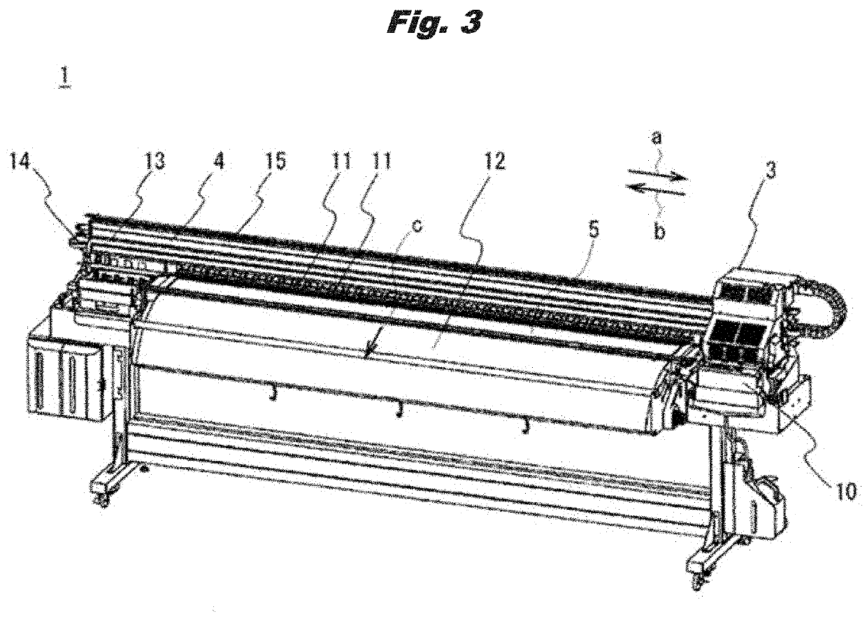
[0142]Next, a second embodiment is described. In the above-described first embodiment, as illustrated in FIG. 2, the first patterns Ar1 and the second patterns Ar2 formed in the recording medium P extend along the medium carrying direction indicated by the arrow c. However, it is also possible that these first patterns Ar1 and second patterns Ar2 are inclined with respect to medium carrying direction. Therefore, in the second embodiment, even when a recording medium P in which the first patterns Ar1 and the second patterns Ar2 are inclined with respect to the medium carrying direction is used, the recording positions of the dots can be appropriately corrected.

[0143]The configuration of the inkjet printer 1 (or recording apparatus) is the same as that in the first embodiment, and a detailed description thereof is omitted. Therefore, in the following, only a method for correcting the recording positions of the dots is described.

2-1. Correction of Recording Position...

first other embodiment

3-1. First Other Embodiment

[0182]In the above-described first embodiment, the reference pattern Pt1 is printed once in the outbound path. However, without being limited to this, it is also possible to print twice in the outbound path such that a basic pattern 101f overlaps a basic pattern 101f. By doing so, the same ink amount is used for the reference pattern Pt1 and for the adjustment pattern Pt2, and the densities of the overlapping patterns 101fb forming the adjustment pattern Pt2 can be more accurately detected.

[0183]Similarly, in the second embodiment, it is also possible that the reference pattern Pt3 is printed twice in the outbound path such that a basic pattern 111f overlaps a basic pattern 111f.


PUM


Abstract

A recording apparatus includes a recording head, a carrying part, a carriage and a detector that optically detects an image recorded on a recording medium, and a controller that obtains a correction value of recording positions of dots from a test pattern, and corrects the recording positions of the dots based on the correction value. The test pattern includes an adjustment pattern and a reference pattern, the adjustment pattern includes multiple overlapping patterns that are each formed by overlapping two basic patterns, the reference pattern is formed of predetermined patterns that each correspond to the multiple overlapping patterns, the correction value of recording positions of dots, which is obtained by the controller, is calculated based on adjustment detection results respectively obtained by detecting the multiple overlapping patterns and a reference detection result obtained by detecting the predetermined pattern forming the reference pattern, and the controller corrects the recording positions of dots based on the correction value.

Description

TECHNICAL FIELD[0001]The present invention relates to a recording apparatus and a correction method, for example, relates to a recording apparatus having an inkjet type recording head that discharges ink onto a recording medium.BACKGROUND[0002]Conventionally, as a recording apparatus of this kind, there is a serial inkjet printer. A serial inkjet printer prints an image on a recording medium while moving an inkjet type recording head back and forth in a main scanning direction perpendicular to a carrying direction (sub-scanning direction) of the recording medium.[0003]In such a serial inkjet printer, for example, an adjustment pattern is printed on a recording medium, and light is irradiated to the printed pattern and reflected light is read with an optical sensor, and, based on a value of the reading, recording positions of dots (for example, landing positions of dots of a outbound path and a inbound path) are corrected (for example, see Patent Document 1).[0004]Further, as a seria...

Claims


Application Information

Patent Timeline
IPC IPC(8): B41J2/045
CPCB41J2/0458B41J2/04558B41J2/2135B41J19/145B41J29/393
Inventor KURIHARA, KAZUTERU
Owner OKI ELECTRIC IND CO LTD
Why Eureka
Try Eureka