
Display apparatus

a technology of display apparatus and display screen, which is applied in the direction of static indicating device, cathode-ray tube indicator, instruments, etc., can solve the problems of deterioration of self-emitting elements such as organic el elements by being driven, deterioration of pixels displaying stationary images more rapidly as compared to other pixels, and no measures are provided in the case of accumulated deterioration amount stored in the memory loss, etc., to achieve high reliability

Inactive Publication Date: 2013-03-07
CANON KK
View PDF4 Cites 2 Cited by
  • Summary
  • Abstract
  • Description
  • Claims
  • Application Information

AI Technical Summary

Benefits of technology

The present invention is about a display screen that can correct the input image data even when there is no memory to store the deterioration amount of the previous image data. The invention calculates the luminance decrease amount for each pixel and stores it in a separate memory. If there is no data in the accumulated luminance decrease amount, the second unit calculates the same luminance decrease amount without accumulating it for each pixel. The input image data can then be appropriately corrected based on either of these two calculations. This invention ensures high reliability and appropriate correction of the input image data even when there is no memory to store the previous data.

Problems solved by technology

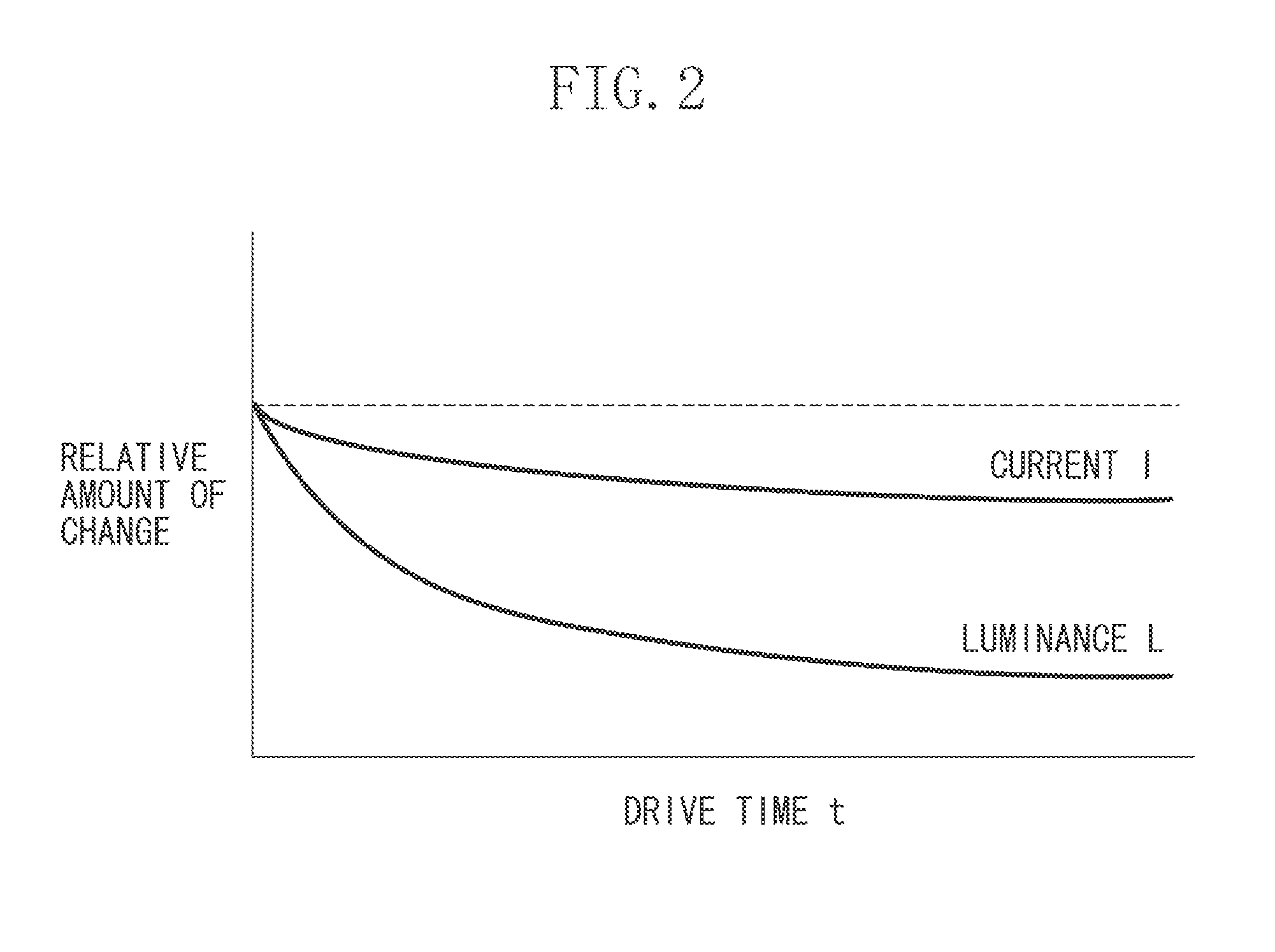
However, the self light-emitting element such as the organic EL element deteriorates by being driven.
In particular, when the self-emitting elements used in the display apparatus continue displaying a stationary image, the pixels displaying the stationary image deteriorate more rapidly as compared to the other pixels.
However, according to such a technique, no measures are provided for the case where the accumulated deterioration amount stored in the memory is lost.
In such a case, the input image data is not corrected, so that reliability of the display apparatus is low.

Method used


Image

  • Display apparatus
  • Display apparatus
  • Display apparatus

Examples


Embodiment Construction

[0018]Various exemplary embodiments, features, and aspects of the invention will be described in detail below with reference to the drawings.

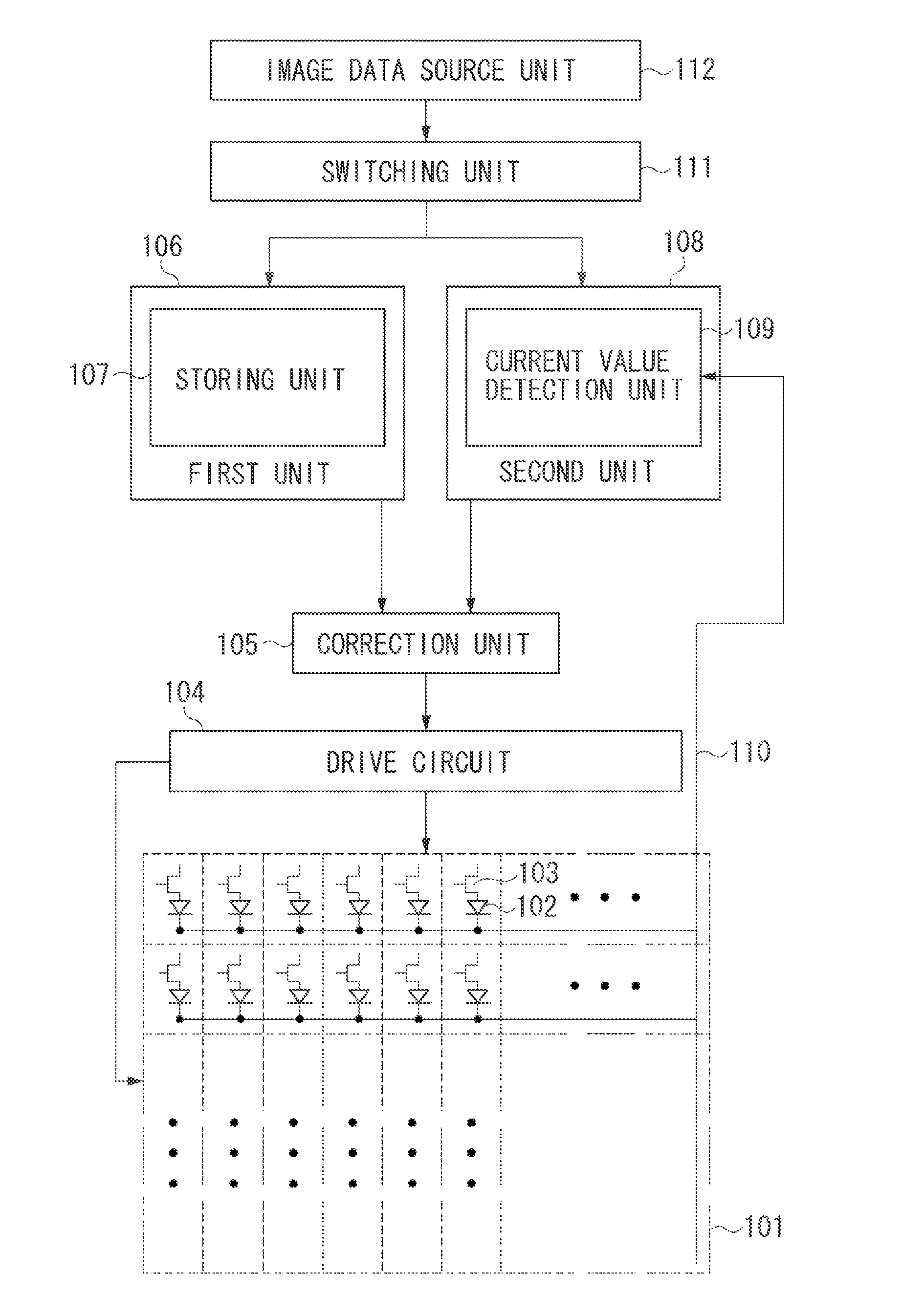
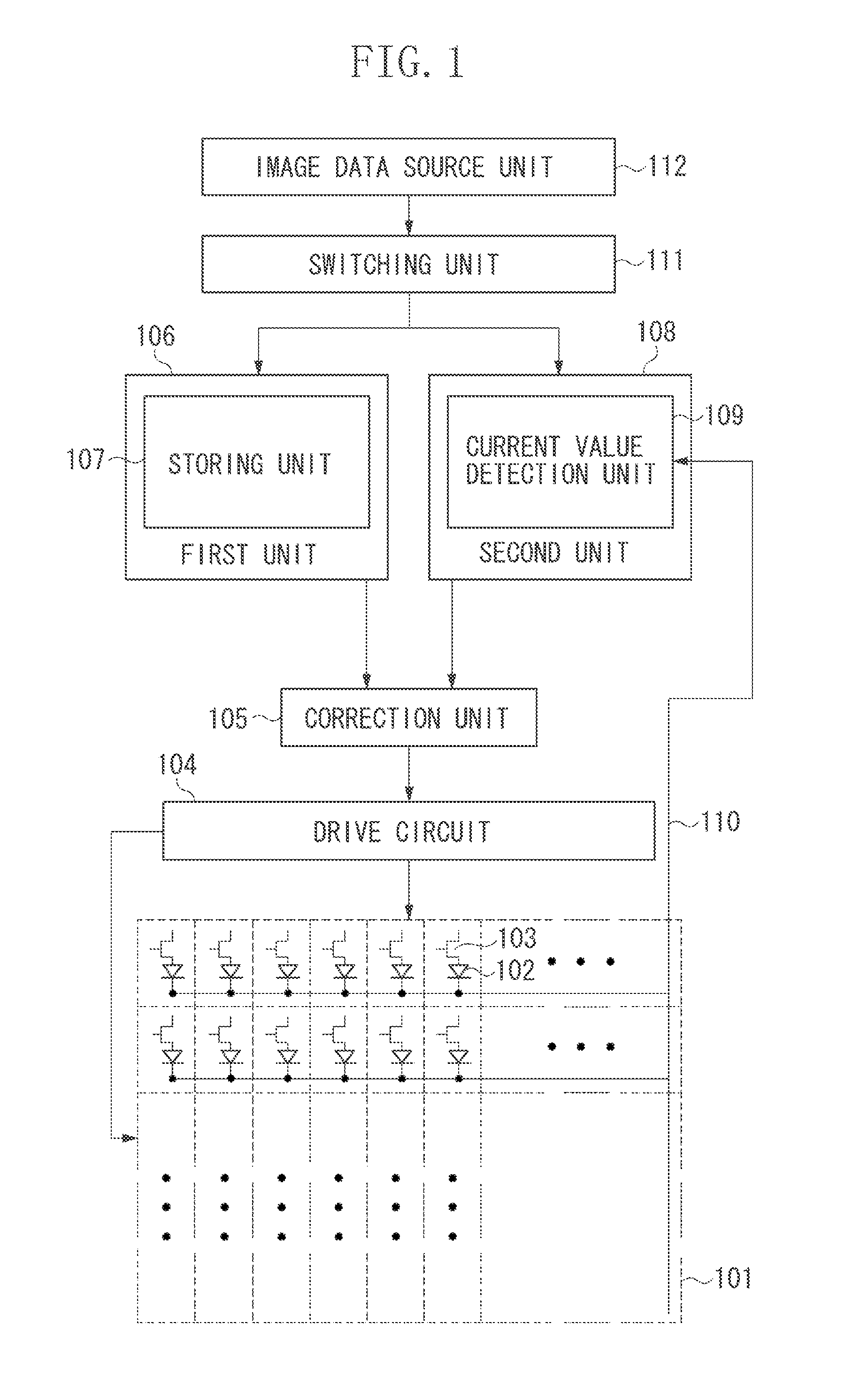
[0019]FIG. 1 illustrates a configuration example of a display apparatus according to an exemplary embodiment of the present invention.

[0020]Referring to FIG. 1, an image display unit 101 includes a plurality of pixels, each having an organic EL element 102 and a pixel circuit 103 which drives the organic EL element 102, arranged in a matrix form. The image display unit 101 displays image data on these pixels. The organic EL element 102 is configured by an organic light emitting layer sandwiched between an anode electrode and a cathode electrode. When a voltage is applied between the electrodes, the organic light emitting layer emits light. According to the present exemplary embodiment, the organic EL element 102 is driven at constant voltage by the pixel circuit 103 performing control to apply constant voltage to the electrodes. The cathode ele...


PUM


Abstract

A display apparatus including an image display unit in which a plurality of pixels have self light-emitting elements is arranged, a first unit configured to accumulate a luminance decrease amount per unit time for each of the pixels, and to set the accumulated amount as a first luminance decrease amount, a second unit configured to detect a current flowing in the self light-emitting element or a voltage value of the self light-emitting element for each of the pixels, and to calculate a second luminance decrease amount from a detected current value or voltage value, and a correction unit configured to correct input image data using one of the first luminance decrease amount or the second luminance decrease amount.

Description

BACKGROUND OF THE INVENTION[0001]1. Field of the Invention[0002]The present invention relates to a display apparatus which displays images using pixels that include self light-emitting elements. In particular, the present invention relates to a display apparatus that corrects an image based on an amount of decrease in luminance, and displays the image.[0003]2. Description of the Related Art[0004]Currently, there is active research and development of self light-emitting display apparatus employing self light-emitting elements such as organic electroluminescence (hereinafter referred to as organic EL) elements. An organic EL display apparatus is configured by an arrangement of a plurality of pixels including the organic EL elements. The organic EL display apparatus has features such as a high-speed responsiveness and a wide viewing angle due to the self light-emitting characteristic, and is expected to be the next-generation display apparatus replacing the conventional liquid crystal ...

Claims


Application Information

Patent Timeline
IPC IPC(8): G09G5/02
CPCG09G3/3225G09G2320/048G09G2320/046
Inventor HIGAKI, TAKUYASHIDO, SHUNICHIMORI, HIDEO
Owner CANON KK
Learn More