
Liquid discharging device, liquid discharging method, and computer program product

Active Publication Date: 2020-08-27
RICOH KK
View PDF0 Cites 0 Cited by
  • Summary
  • Abstract
  • Description
  • Claims
  • Application Information

AI Technical Summary

Benefits of technology

The present invention provides a liquid discharging device that can create images by discharging liquid onto a recording medium. The device has multiple head modules with nozzles that discharge liquid of different colors and processing circuitry to acquire image data. An allocation system assigns a row of liquid droplets to dots of the image data, ensuring that the liquid droplets closest to the guide are equal in ratio to or higher than those from other head modules. The technical effect is that the device can produce high-quality images with consistent liquid droplet ratios using a simple and efficient allocation system.

Problems solved by technology

The serial-scanning ink jet recording device performs recording while the head units moves on a recording medium, which may affect recording quality due to various mechanical factors.
This may be not a significant matter to a serial-scanning ink jet recording device including a conventional integrated shorter-length head, however, it may be an important issue to address to a serial-scanning ink jet recording device including a connected longer-length head.
Measures against such an issue will be improving device-body stiffness, installing head units having less variation, or machining parts and components at higher accuracy, all of which will result in largely raising costs.
Thus, serial-scanning ink jet recording devices including connected longer-length heads cannot be provided at a desirable, relatively low price.

Method used


Image

  • Liquid discharging device, liquid discharging method, and computer program product
  • Liquid discharging device, liquid discharging method, and computer program product
  • Liquid discharging device, liquid discharging method, and computer program product

Examples


first modification

[0098]FIG. 15 is a diagram illustrating a multi-pass recording control of an ink jet recording device according to a first modification. Multi-pass recording control of the ink jet recording device 10 according to the present modification will be described with reference to FIG. 15.

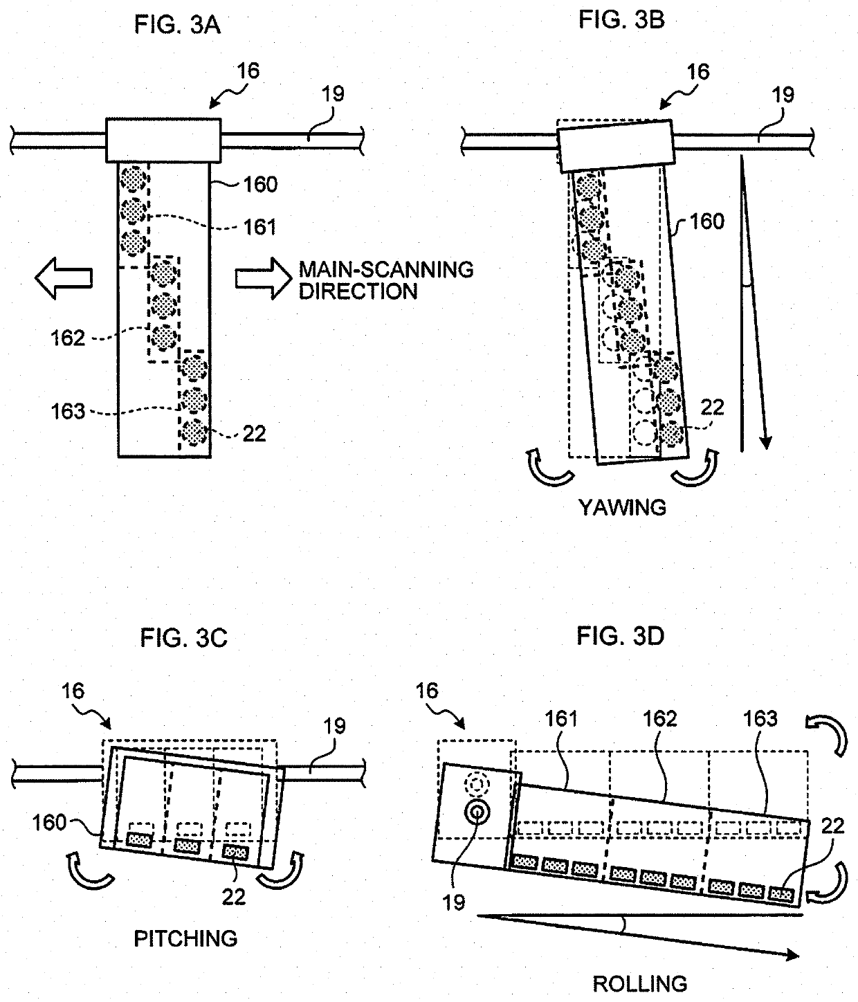
[0099]As described above with reference to (a) to (d) of FIG. 3, the more distanced from the guide rod 19 the recording head 16 is, the larger the mechanical fluctuation is. That is, the use of a head module closer to the guide rod 19 increases ink-droplet discharging accuracy. In view of this, in the present modification among the head modules of the recording head 16, the first head module 161 closest to the guide rod 19 is preferentially set to form dots of the same dot row, as illustrated in FIG. 15. That is, a large part (a half in the example of FIG. 15) of an image is formed from the ink droplets discharged from the first head module 161, to thereby ensure general image quality. The second head mod...

second modification

[0102]FIG. 16 are diagrams (a) and (b) illustrating a multi-pass recording control of an ink jet recording device according to a second modification. Multi-pass recording control of the present modification is more advanced than that in (b) of FIG. 14 in which scanning is performed in a divided manner, three times in the main-scanning direction and six times in the sub-scanning direction, i.e., a total of 18 scans. Such a control will be described with reference to (a) and (a) of FIG. 16.

[0103]The diagram (a) of FIG. 16 illustrates the multi-pass recording control illustrated in (b) of FIG. 14. The recording head 16, capable of discharging ink droplets to attain recording at main-scanning resolution by one main-scanning, can eject ink droplets onto pixels of dot data in the same position by multiple scans in an overlaid manner. In view of this, in the present modification the allocator 204 performs rendering such that the first head module 161 ejects ink droplets onto the same dot r...

third modification

[0107]FIG. 17 illustrates diagrams (a) and (b) of a multi-pass recording control of an ink jet recording device according to a third modification. Multi-pass recording control of the present modification is more advanced than that of the first modification with reference to FIG. 15, which will be described with reference to (a) and (b) of FIG. 17.

[0108]The diagram (a) of FIG. 17 illustrates the multi-pass recording control illustrated in FIG. 15. As mentioned above, the recording head 16, capable of discharging ink droplets to attain recording at main-scanning resolution by one main-scanning, can eject ink droplets onto pixels of dot data in the same position by multiple scans in an overlaid manner. In view of this, in the present modification the allocator 204 performs rendering such that the first head module 161 ejects ink droplets on the dot rows of dots formed by both the second head module 162 and the third head module 163 as illustrated in (b) of FIG. 17. To be specific, the ...


PUM


Abstract

A liquid discharging device discharges a liquid onto a recording medium for image formation, and includes head modules each including a nozzle array that discharges a liquid of at least one color, the head modules being connected in a direction of the nozzle array from one of the head modules, the one supported by a guide extending in a main-scanning direction; and processing circuitry functioning as an acquirer that acquires image data based on which the image is formed, and an allocator that allocates, to dots of the image data, a row of liquid droplets discharged from one of the head modules closest to the guide in a sub-scanning direction, such that the liquid droplets discharged from the head module closest to the guide are equal to or higher in ratio than the liquid droplets discharged from each head module other than the head module closest to the guide.

Description

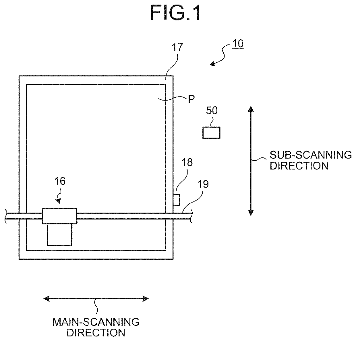
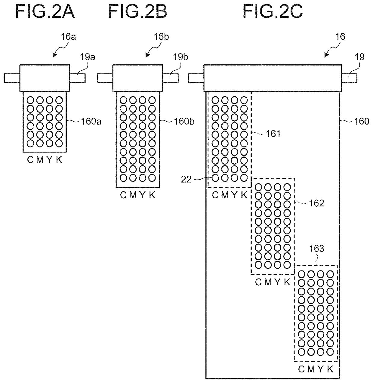
CROSS-REFERENCE TO RELATED APPLICATIONS[0001]The present application claims priority under 35 U.S.C. § 119 to Japanese Patent Application No. 2019-034392, filed on Feb. 27, 2019. The contents of which are incorporated herein by reference in their entirety.BACKGROUND OF THE INVENTION1. Field of the Invention[0002]The present invention relates to a liquid discharging device, a liquid discharging method, and a computer program product.2. Description of the Related Art[0003]Conventionally, a serial-scanning ink jet recording device includes nozzle arrays or head units of different colors arranged in a direction perpendicular to the arrays or the units to perform recording or printing by scanning (main scanning) in such a direction (main-scanning direction) while conveying (sub-scanning) a recording medium in a direction (sub-scanning direction) perpendicular to the main-scanning direction. In recent years, head units have been grown in size for the sake of productivity improvement. One ...

Claims


Application Information

Patent Timeline
IPC IPC(8): B41J2/21B41J2/14
CPCB41J2/2132B41J2/14B41J2/2103B41J2/2054B41J2/15G06K15/102G06K15/107
Inventor HIRANO, MASANORI
Owner RICOH KK
Learn More