Check patentability & draft patents in minutes with Patsnap Eureka AI!

Sound source localization device, sound source localization method, and program

Active Publication Date: 2020-08-27
HONDA MOTOR CO LTD
View PDF0 Cites 0 Cited by
  • Summary
  • Abstract
  • Description
  • Claims
  • Application Information

AI Technical Summary

Benefits of technology

The technical effects of this patent are to provide a device, method, and program that can use deep learning and phase information to locate the source of a sound. This can be useful in identifying the location of a sound in a noisy environment, or improving the quality of sound recognition.

Problems solved by technology

As described above, in conventional technologies described in Non-Patent Documents 1 and 2, since information other than phase information is input to the neural network, important phase information cannot be utilized for sound source localization processing.

Method used


Image

  • Sound source localization device, sound source localization method, and program
  • Sound source localization device, sound source localization method, and program
  • Sound source localization device, sound source localization method, and program

Examples


Embodiment Construction

[0034]In the following description, embodiments of the present invention will be described with reference to the drawings.

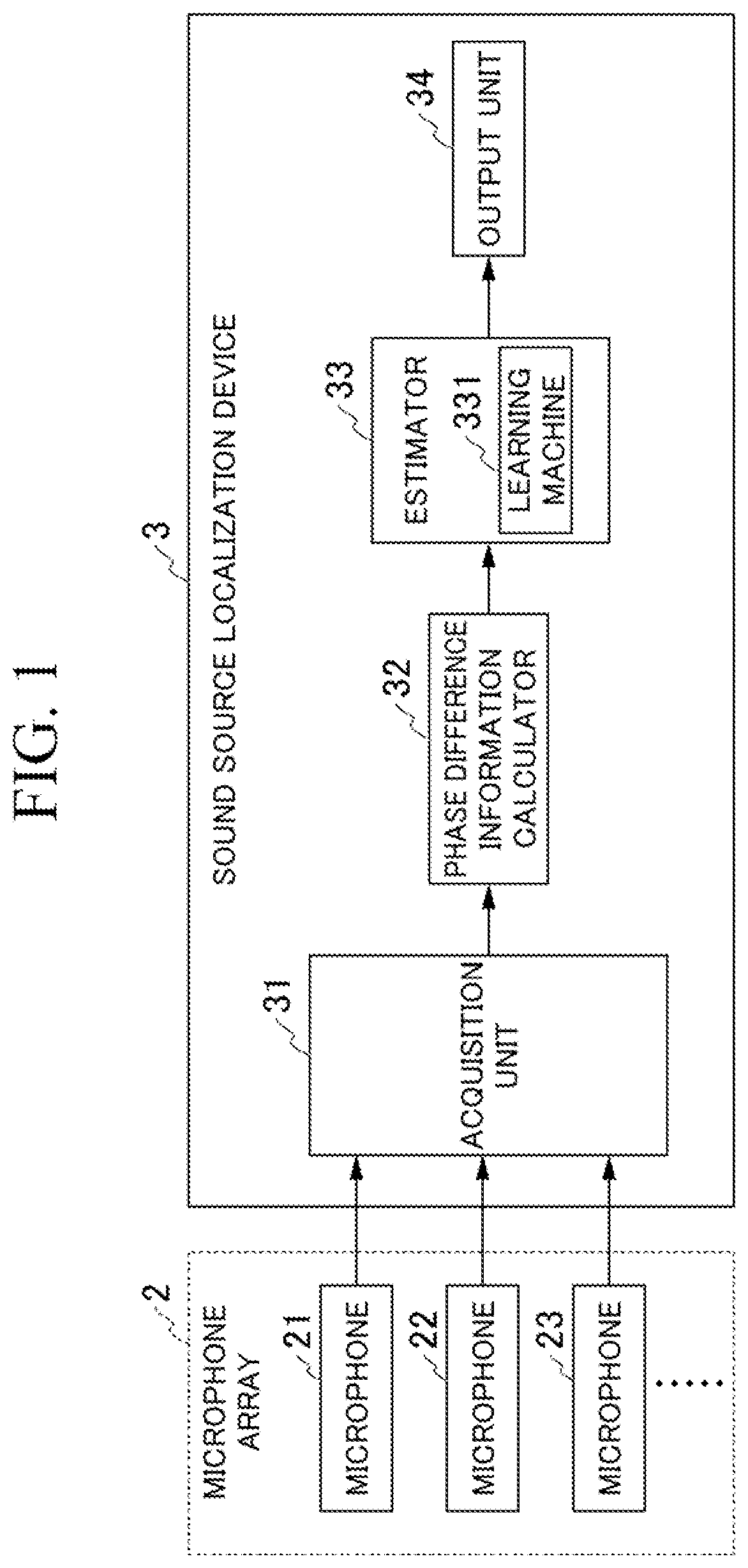
[0035]FIG. 1 is a block diagram which shows a configuration example of a sound source localization device 3 according to the present embodiment. As shown in FIG. 1, the sound source localization device 3 includes an acquisition unit 31, a phase difference information calculator 32, an estimator 33, and an output unit 34. A microphone array 2 is connected to the sound source localization device 3 in a wireless or wired manner.

[0036]The microphone array 2 includes M (M is an integer of two or more) microphones (microphones 21, 22, 23, . . . , and so forth). The microphone array 2 collects acoustic signals emitted by a sound source and outputs the collected acoustic signals of M channels to the sound source localization device 3.

[0037]The sound source localization device 3 estimates a direction of the sound source using the acquired acoustic signals.

[0038]The acquis...


PUM


Abstract

A sound source localization device includes an acquisition unit configured to acquire acoustic signals of M channels (M is an integer equal to or greater than one), a phase difference information calculator configured to perform a short-time Fourier transform on the acoustic signals of M channels and to convert a time domain into a frequency domain including phase information, and an estimator configured to input phase information of the acoustic signals subjected to the short-time Fourier transform to a deep learning machine and to perform sound source localization of the acoustic signals using the deep learning machine where input follows a von Mises distribution.

Description

CROSS-REFERENCE TO RELATED APPLICATION[0001]Priority is claimed on Japanese Patent Application No. 2019-034717, filed Feb. 27, 2019, the content of which is incorporated herein by reference.BACKGROUND OF THE INVENTIONField of the Invention[0002]The present invention relates to a sound source localization device, a sound source localization method, and a program.Description of Related Art[0003]Sound source localization is performed using a microphone array composed of a plurality of microphones. An outline of sound source localization processing in the prior art will be described using FIGS. 12 to 14. FIG. 12 is a diagram which shows sound collection using the microphone array. FIG. 13 is a diagram which shows an example procedure of conventional sound source localization processing.[0004]In sound source localization processing, an acoustic signal 902 generated by the sound source 901 is subjected to sound collection using a microphone array 903. As shown in FIG. 12, the microphone a...

Claims


Application Information

Patent Timeline
IPC IPC(8): H04R3/00H04R1/40G06N20/00G06N3/04
CPCG06N20/00G06N3/04H04R3/005H04R1/406H04R2430/23G06N3/08G06N3/047G06N3/048G06N3/044
Inventor NAKADAI, KAZUHIROMASAKI, SHUNGOKOJIMA, RYOSUKESUGIYAMA, OSAMUITOYAMA, KATSUTOSHINISHIDA, KENJI
Owner HONDA MOTOR CO LTD
Features
  • R&D
  • Intellectual Property
  • Life Sciences
  • Materials
  • Tech Scout
  • Unparalleled Data Quality
  • Higher Quality Content
  • 60% Fewer Hallucinations
Learn More