Check patentability & draft patents in minutes with Patsnap Eureka AI!

Cutter mechanism for a printer and methods of cutting paper media in a printer

a technology of cutter mechanism and printer, which is applied in the direction of printing, metal working apparatus, other printing apparatus, etc., can solve the problems of guillotine knife blades that are prone to jamming and difficult to service, and it is difficult to load paper into printers with guillotine knife blades

Active Publication Date: 2020-09-10
TRANSACT TECH
View PDF0 Cites 0 Cited by
  • Summary
  • Abstract
  • Description
  • Claims
  • Application Information

AI Technical Summary

Benefits of technology

The present invention is a cutter mechanism for a printer that includes a rotary cutter and a straight blade assembly. The straight blade is mounted for rotation and cooperation with the rotary cutter. When the printer mechanism cover is opened, the straight blade is moved away from the rotary cutter and a portion of the cover impacts the straight blade assembly, causing it to move. The cutter mechanism also includes a biasing mechanism for biasing the straight blade against the rotary cutter in the closed position of the cover. The invention also includes methods for cutting paper media in a printer using the cutter mechanism. The technical effects of the invention include improved cutting performance and an improved user experience.

Problems solved by technology

While such guillotine knife blades are generally simpler and less expensive than rotary knife blades, such guillotine knife blades are prone to jamming and difficult to service.
It is also typically difficult to load paper into printers having guillotine knife blades.

Method used


Image

  • Cutter mechanism for a printer and methods of cutting paper media in a printer
  • Cutter mechanism for a printer and methods of cutting paper media in a printer
  • Cutter mechanism for a printer and methods of cutting paper media in a printer

Examples


Embodiment Construction

[0026]The ensuing detailed description provides exemplary embodiments only, and is not intended to limit the scope, applicability, or configuration of the invention. Rather, the ensuing detailed description of the exemplary embodiments will provide those skilled in the art with an enabling description for implementing an embodiment of the invention. It should be understood that various changes may be made in the function and arrangement of elements without departing from the spirit and scope of the invention as set forth in the appended claims.

[0027]The present invention relates to a cutter mechanism for a printer and corresponding methods for cutting paper media in a printer using such a cutter mechanism.

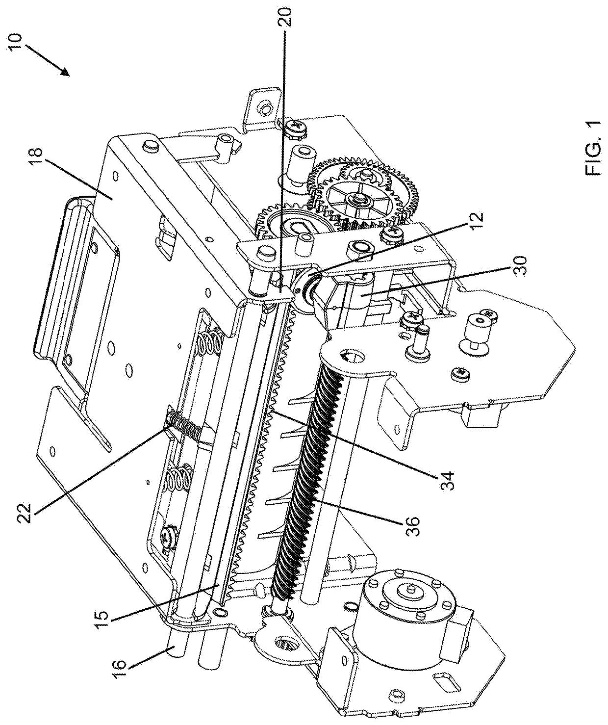
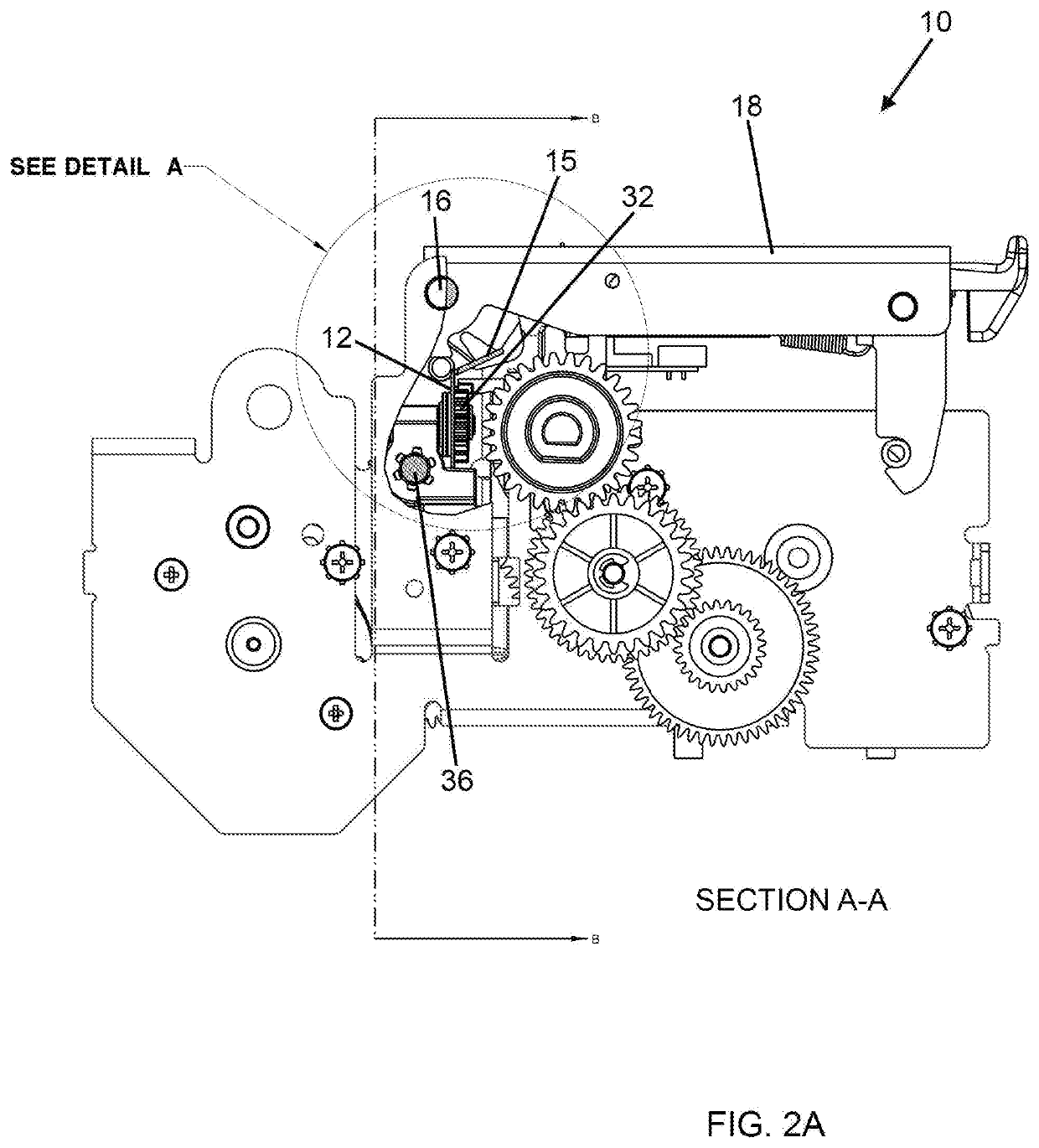
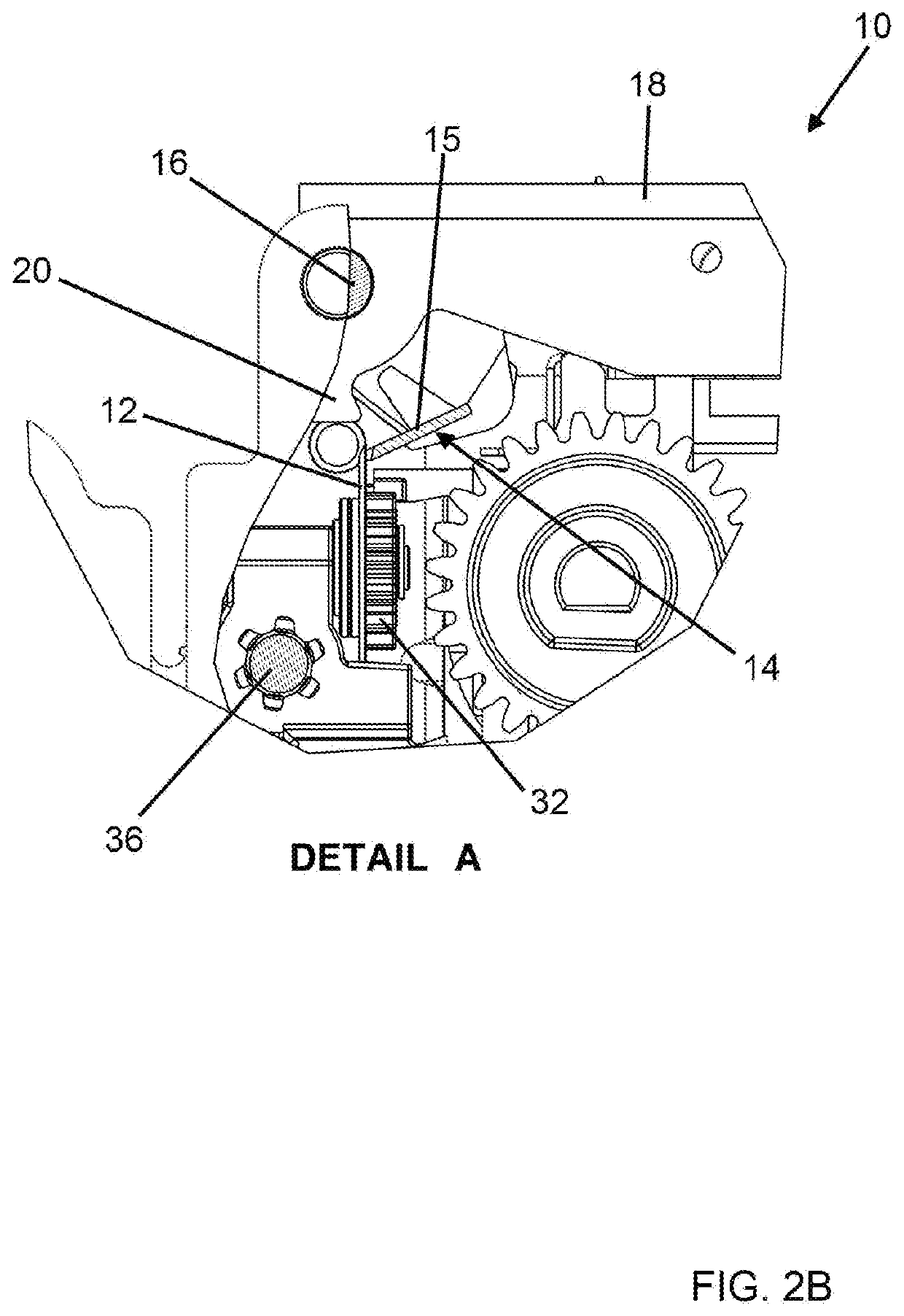
[0028]An example embodiment of a cutter mechanism 10 for a printer in accordance with the present invention is shown in FIGS. 1-7. The cutter mechanism 10 comprises a rotary cutter 12 and a straight blade assembly 14. The rotary cutter 12 may be mounted for rotation about a rotatio...


PUM


Abstract

A cutter mechanism for a printer is provided. The cutter mechanism comprises a rotary cutter and a straight blade assembly. The rotary cutter may be mounted for rotation about a rotation axis and for translation across at least a portion of a width of a paper path perpendicular to the rotation axis. The straight blade assembly may be mounted for rotation about a shaft and adapted to cooperate with the rotary cutter. The straight blade assembly comprises a straight blade extending across the width of the paper path. A printer mechanism cover is mounted coaxially on the shaft so as to be movable between a closed position and an open position. A portion of the cover may impact the straight blade assembly when the cover is moved from the closed position to the open position, causing the straight blade to be moved away from the rotary cutter.

Description

BACKGROUND OF THE INVENTION[0001]The present invention relates to the field of cutter mechanisms for printers. More specifically, the present invention relates to a cutter mechanism for cutting paper media in a printer and methods of cutting paper media in a printer using such a cutter mechanism.[0002]High speed printers, such as inkjet, thermal, dye sublimation and dot matrix printers are used to provide vouchers, coupons, tickets, receipts and the like (all generally referred to herein as “tickets”) to consumers. Such printers typically use a roll of paper media which is cut by a cutter. Different types of cutters may be used in such printers, including a rotary cutter or a guillotine knife blade type cutter. The guillotine knife cutters typically employ a fixed blade and a movable blade which is displaced in the direction of, and engages against, the fixed blade during a cutting action after the ticket is printed on the paper media. While such guillotine knife blades are generall...

Claims


Application Information

Patent Timeline
Patent Type & Authority Applications(United States)
IPC IPC(8): B26D1/22B26D1/00B26D7/26B41J11/70
CPCB26D2007/005B26D7/2614B26D2001/0066B26D1/225B41J11/706B26D1/0006
Inventor ZACH, PETER
Owner TRANSACT TECH
Features
  • R&D
  • Intellectual Property
  • Life Sciences
  • Materials
  • Tech Scout
  • Unparalleled Data Quality
  • Higher Quality Content
  • 60% Fewer Hallucinations
Learn More