Injection molding mold apparatus and method for manufacturing injection-molded article

Active Publication Date: 2020-09-10
TOKAI KOGYO CO LTD
View PDF0 Cites 0 Cited by
  • Summary
  • Abstract
  • Description
  • Claims
  • Application Information

AI Technical Summary

Benefits of technology

The present patent aims to provide an injection molding mold apparatus and method that can mold injection-molded articles with exposed surfaces without generating bumps or increasing cost. By moving the slide mold in a different direction than the insert member, the variations of the insert member can be absorbed by the slide mold and pressing member, resulting in a smooth molding process without bumps. This also eliminates the need for a separate resin member to prevent bumps, reducing costs and avoiding the risk of breakage.

Problems solved by technology

Therefore, there is a defect that the insert molding cannot be performed without generating a burr on the exposed portion of the insert member which varies in two different directions.
However, in a case of this method, in addition to necessity of manufacturing the resin member separately, work of setting the resin member at a predetermined position in the molds is required.
Therefore, there is a disadvantage that a manufacturing cost of the injection-molded article is likely to increase.
Further, since a defect may occur in which a separate body is damaged or misaligned during injection molding, there is also a risk that a yield of a product may be deteriorated, which may result in an increase in a cost.

Method used


Image

  • Injection molding mold apparatus and method for manufacturing injection-molded article
  • Injection molding mold apparatus and method for manufacturing injection-molded article
  • Injection molding mold apparatus and method for manufacturing injection-molded article

Examples


first embodiment

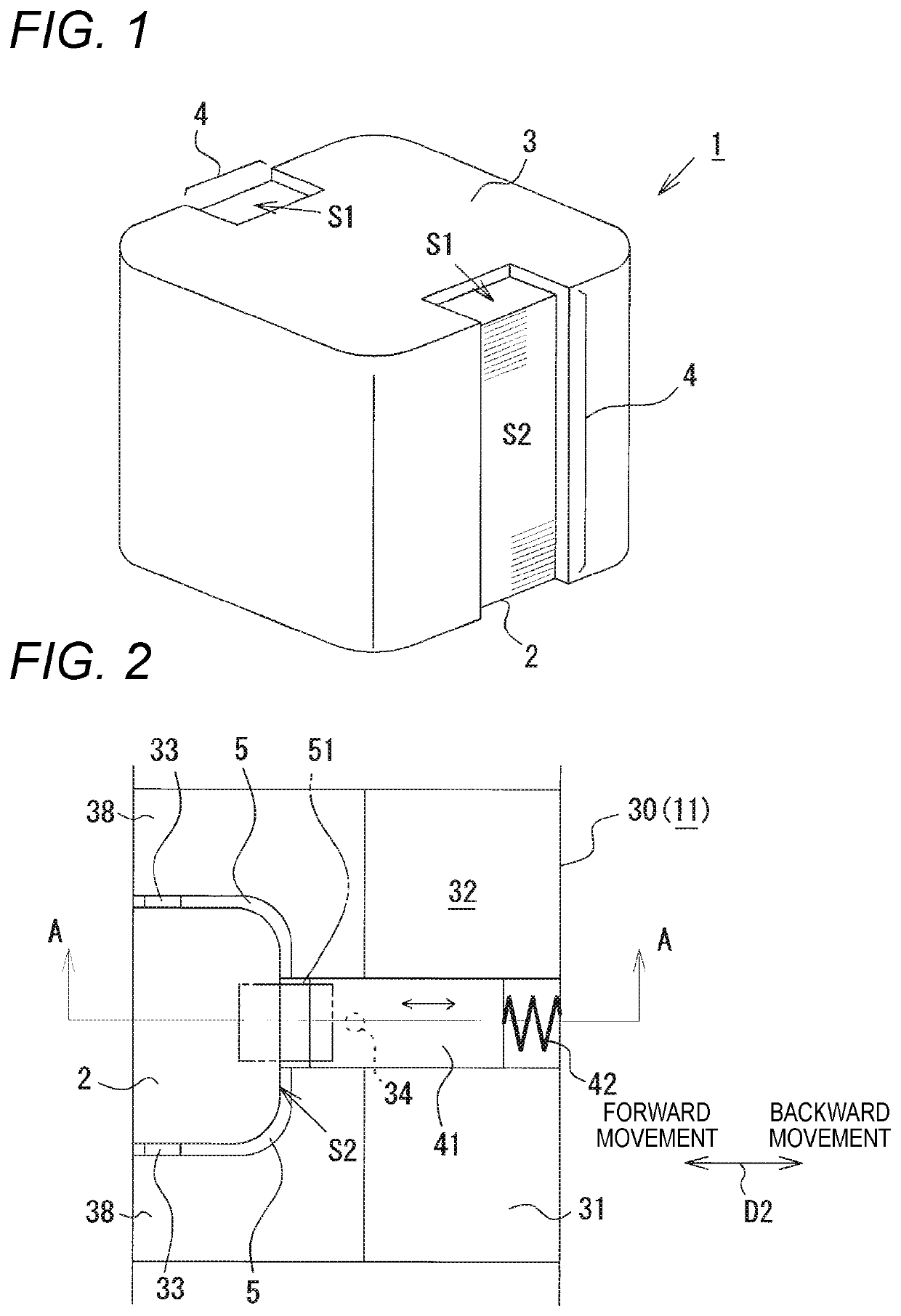
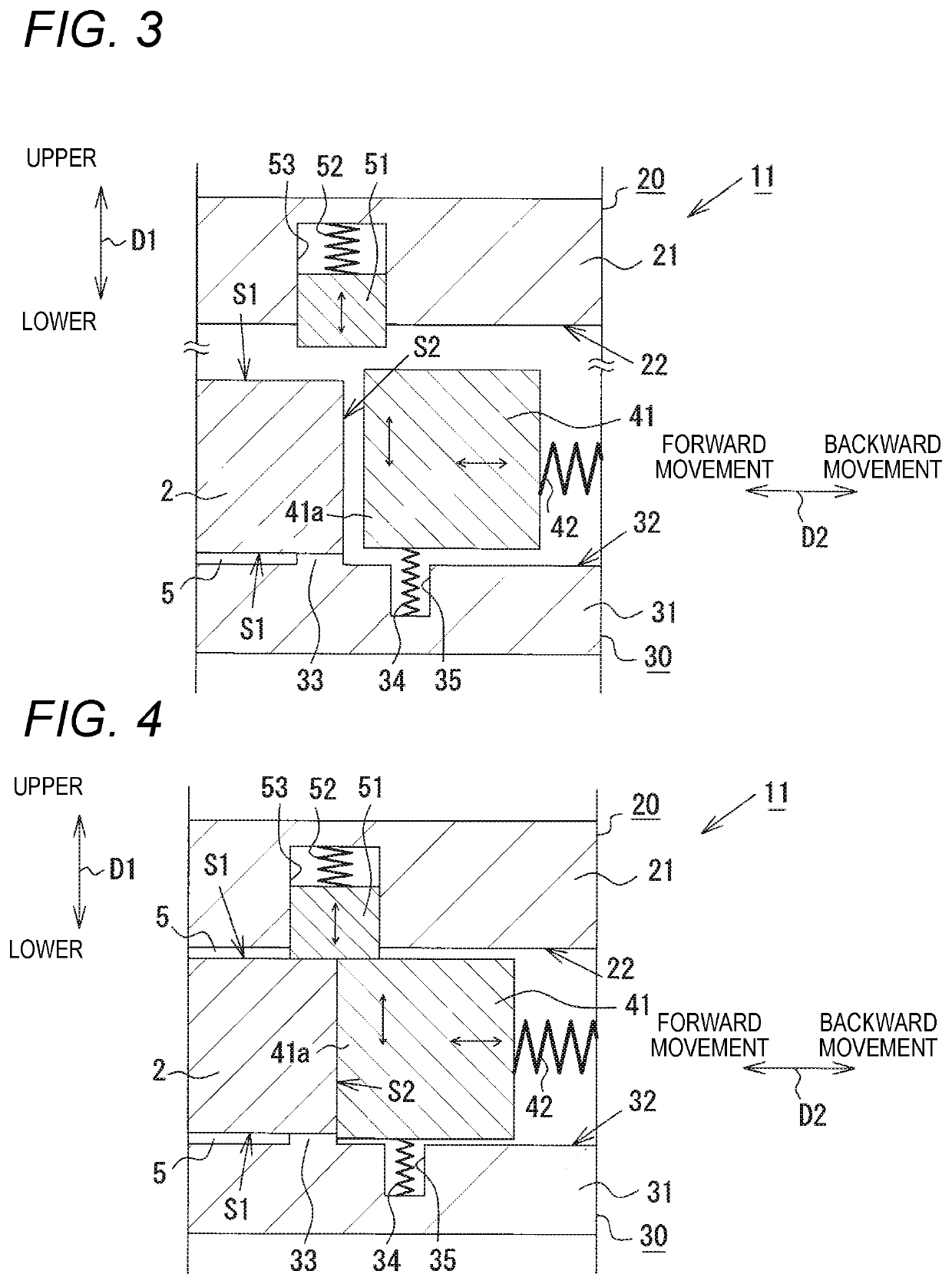
[0027]Hereinafter, a mold apparatus for molding an injection-molded article according to an embodiment of the present disclosure will be described in detail with reference to FIGS. 1 to 5.

[0028]FIG. 1 shows an injection-molded article 1 manufactured using a mold apparatus 11 in the present embodiment. The injection-molded article 1 is an insert molded article manufactured by an insert molding method that is a type of injection molding method, and is a substantially cubic structure in which an insert member 2 is embedded in a coating resin 3 made of a thermoplastic resin. The thermoplastic resin that is a material for molding the coating resin 3 is not particularly limited. For example, a PPS resin, or a PBT resin is used. In order to reduce a thermal expansion coefficient, an inorganic substance such as glass fibers or glass particles may be added to these resin materials as a filler. As the insert member 2, any insert member can be selected without a particular limitation on a mate...

second embodiment

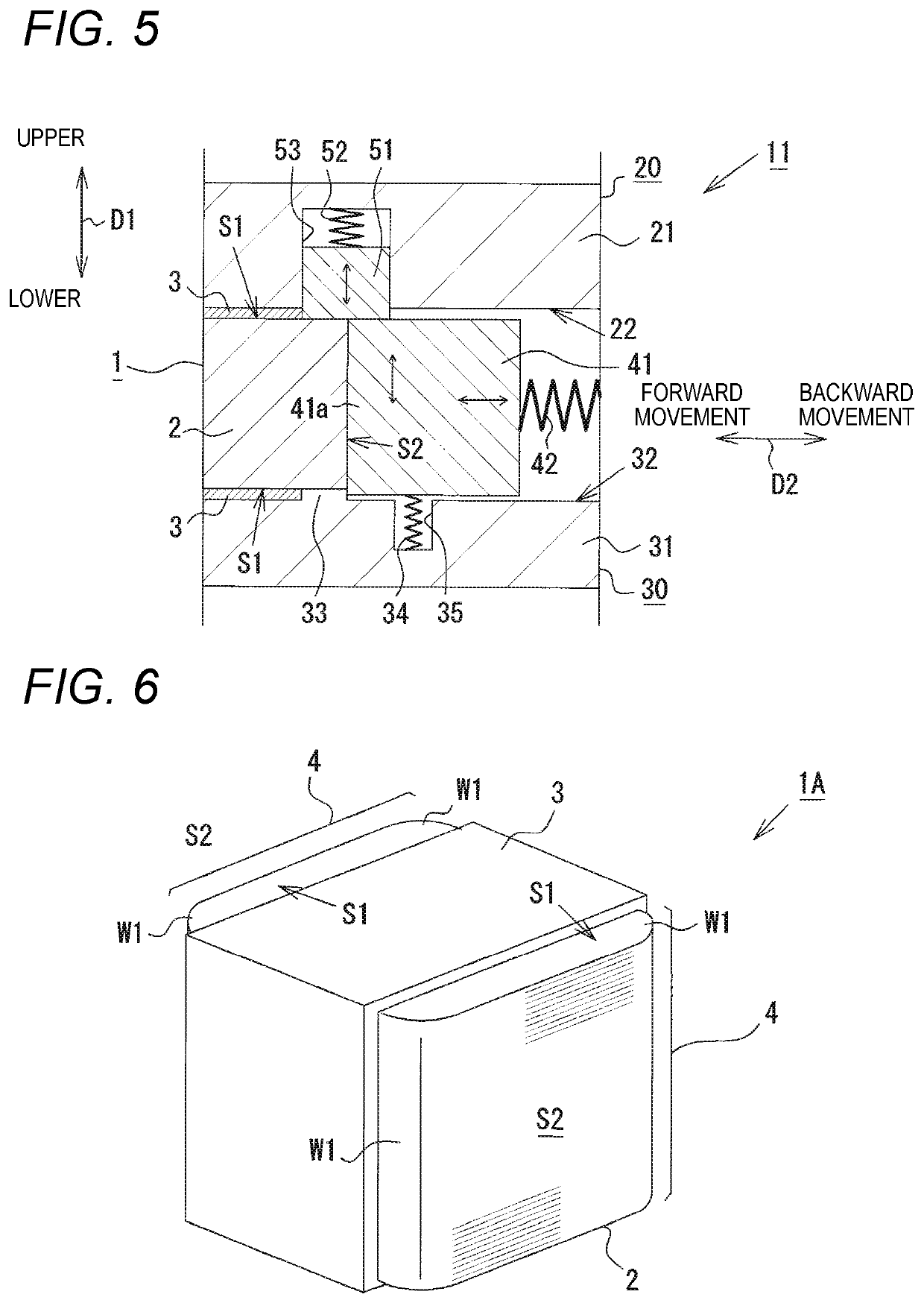
[0046]Hereinafter, a mold apparatus 11A for molding an injection-molded article according to a second embodiment of the present disclosure will be described in detail with reference to FIGS. 6 to 10. In the present embodiment, portions different from those of the first embodiment will be described in detail, while common portions are denoted by the same reference numerals, and detailed description thereof will be omitted.

[0047]FIG. 6 shows an injection-molded article 1A manufactured using a mold apparatus 11A in the present embodiment. The insert member 2 is also mostly covered by the coating resin 3, and has two portions (exposed portions 4) that expose parts of the insert member 2 to outside. Although each of the exposed portions 4 in the present embodiment is formed over two continuous surfaces on the insert member 2, the exposed portion 4 extends over a range wider than that of the first embodiment. In the injection-molded article 1A, curved portions W1 of the second surfaces S2...

third embodiment

[0060]Hereinafter, a mold apparatus for molding an injection-molded article according to an embodiment of the present disclosure will be described in detail with reference to FIGS. 11 to 12. In the present embodiment, portions different from those of the embodiment described above will be described in detail, while common portions are denoted by the same reference numerals, and detailed description thereof will be omitted.

[0061]FIG. 11 shows an injection-molded article 1C manufactured using a mold apparatus 11C in the present embodiment. The injection-molded article 1C has a cylindrical shape. As the insert member 2, a laminated core formed by laminating a large number of annular core pieces is used. The injection-molded article 1C includes only one exposed portion 4 formed over two continuous surfaces. The exposed portion 4 does not expose the second surface S2 of the insert member 2 over an entire length of the insert member 2 in an upper-lower direction, but exposes the second su...


PUM

PropertyMeasurementUnit
Pressureaaaaaaaaaa

Abstract

An injection molding mold apparatus including: a first mold and a second mold forming a cavity into which thermoplastic resin is configured to be injected; a slide mold provided on at least one of the first and second molds, capable of moving back and forth in a direction intersecting a mold opening and closing direction, and forming a part of the cavity while being in pressure contact with an insert member during molding; and a pressing member provided at a portion where the slide mold is not provided among portions of the first and second molds that face each other and at a position corresponding to a tip end portion of the slide mold, being movable in the mold opening and closing direction, and pressing and moving the tip end portion in the mold opening and closing direction when the first and second molds are closed.

Description

CROSS-REFERENCE TO RELATED APPLICATIONS[0001]This application claims priority from Japanese Patent Application No. 2019-042159 filed on Mar. 8, 2019, the entire contents of which are incorporated herein by reference.TECHNICAL FIELD[0002]The present disclosure relates to an injection molding mold apparatus used when manufacturing an injection-molded article in which a part of an insert member is exposed to outside of a coating resin, and a method for manufacturing the injection-molded article by using the injection molding mold apparatus.BACKGROUND ART[0003]In related art, as one type of method for manufacturing an injection-molded article, an insert molding method using a mold apparatus is well known. The injection-molded article manufactured by the insert molding method has a structure in which an insert member is embedded in a coating resin made of a thermoplastic resin. Examples of products of the injection-molded article manufactured by the insert molding method can include elec...

Claims


Application Information

Patent Timeline
IPC IPC(8): B29C45/14B29C45/26
CPCB29C45/14065B29C45/26B29C45/0025B29C45/14336B29C45/332B29C45/66H05K7/2039B29C2045/14163B29C45/33
Inventor HIRASAWA, KAZUO
Owner TOKAI KOGYO CO LTD
Why Eureka
Try Eureka