Lower cushion of a pile driving rig

a technology of driving rig and lower cushion, which is applied in the direction of bulkhead/pile, construction, foundation engineering, etc., can solve the problems of wasting resources, wasting resources, and eventually catching fire, so as to reduce the risk of fire, and prolong the useful life

Active Publication Date: 2020-09-10
JUNTTAN OY
View PDF2 Cites 0 Cited by
  • Summary
  • Abstract
  • Description
  • Claims
  • Application Information

AI Technical Summary

Benefits of technology

[0005]The purpose of the invention is to achieve a pile driving rig lower cushion that has a longer useful life than wooden lower cushions but that can be kept safely and securely in place in the drive cap housing before fitting the pile into the drive cap housing.
[0006]The purpose of the invention is achieved through a pile driving rig lower cushion that has been manufactured from a material whose modulus of elasticity is 500-3,500 MPa and whose flexibility has been locally increased at least in one direction such that the lower cushion can be compressed in said at least one direction such that it fits inside the drive cap meant for it, between at least two opposite interior surfaces located therein and remains, through the effect of the friction forces created by the compressive force exerted on these surfaces from the lower cushion, safely in the drive cap housing and securely in place also when the pile is not fitted in the drive cap housing. To put it more precisely, the pile driving rig lower cushion according to the invention is characterized by what has been presented in the independent claim 1. The dependent claims 2-18 present some advantageous embodiments of the lower cushion according to the invention.
[0007]The advantage of the pile driving rig lower cushion according to the invention is that it eliminates the fire risks associated with lower cushions realized in the known manner, the replacement of the wooden lower cushions that slows down the pile driving process and the need to transport and store large quantities of lower cushions in the worksite area to be piled. In addition, compared to known lower cushions made of plastic, there is the advantage that the lower cushion does not cause safety risks because it remains in the drive cap housing also when the pile is not fitted in the drive cap housing (usually when the driving of the pile into the ground is started).

Problems solved by technology

The purpose of the lower cushion is to reduce the compressive stress peak of the first shock wave following the blow, which otherwise might cause the end of the pile to crumble, thus damaging the pile so as to make it unfit for use.
The problem with a lower cushion made of wood is that it starts to heat up as the pile driving proceeds, and often it eventually catches fire.
Furthermore, a wooden lower cushion loses its flexibility in any case, usually during the driving of one pile or, in the worst-case scenario, even partway through driving the same pile.
Therefore, when using lower cushions made of wood, there must be a large quantity of them on the worksite.
Replacing them uses up work time and thus slows down the progress of the pile driving work.
In particular, if the lower cushion must be replaced partway through driving the same pile, it is detrimental, because then the hammer must be lifted off from on top of the pile partway through driving the pile.
In addition, a large quantity of lower cushions made of wood must be transported to the worksite and stored there during the pile driving work.
However, the problem with them is that it is difficult to make a lower cushion with suitably sized material properties remain in place in the drive cap housing at the stage when the pile has not yet been installed in its place in the drive cap housing.
A lower cushion falling down from the upper part of the leader (from a height of up to 30 metres) causes a significant safety risk for the persons around the pile driver.

Method used


Image

  • Lower cushion of a pile driving rig
  • Lower cushion of a pile driving rig
  • Lower cushion of a pile driving rig

Examples


Embodiment Construction

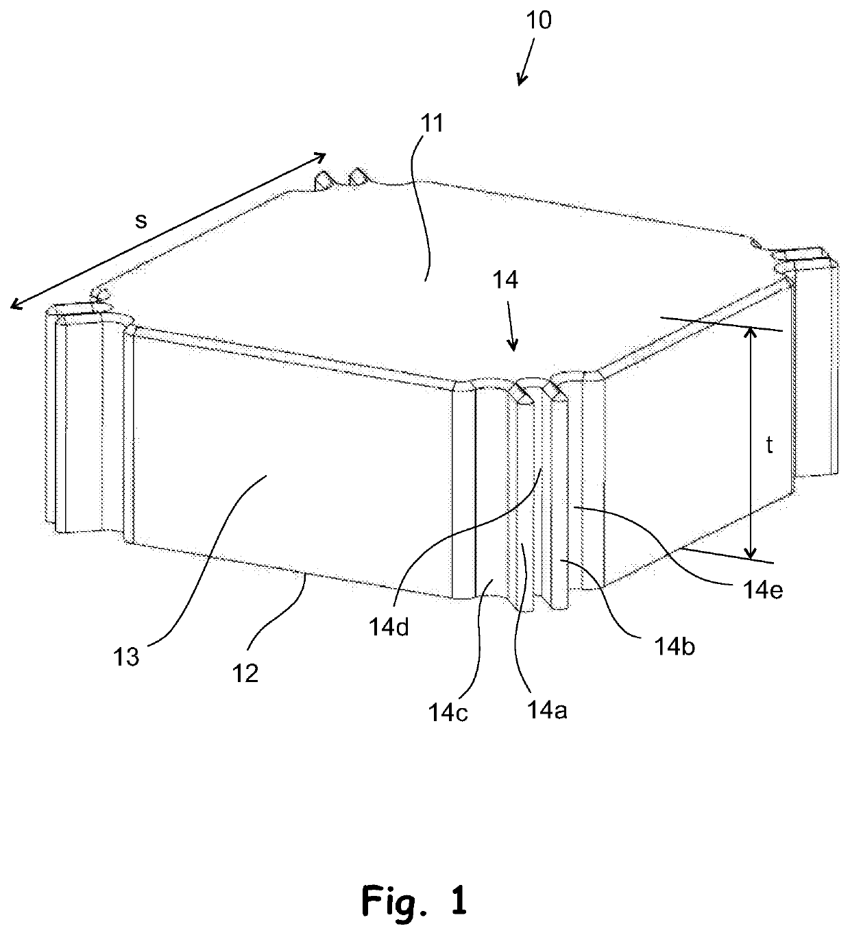
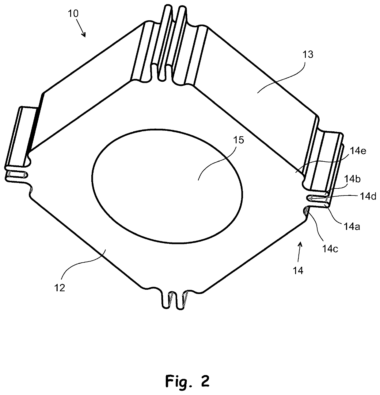
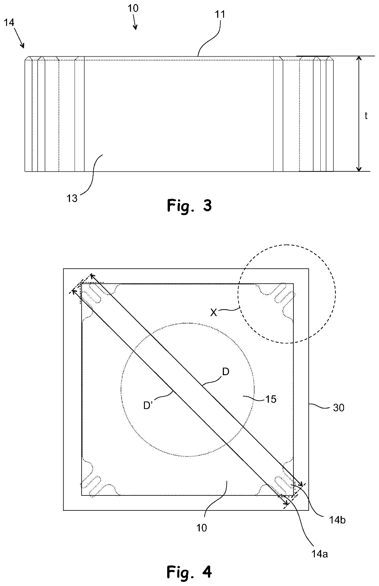
[0017]FIGS. 1-5 show a pile driving rig lower cushion 10 according to the invention, which, in this case, has been made of plastic whose modulus of elasticity is comprised between 500 and 3,500 MPa and which is a single piece made of monomaterial. The lower cushion 10 shown in FIGS. 1-5 has been designed so that it can be fitted, in the manner shown in FIGS. 4 and 5, inside the drive cap housing 30 with a rectangular cross section located in the lower part of the pile driving rig hammer, such that its first end surface, i.e., in this case, top surface 11 comes against the drive cap (not shown in the figures) located above the drive cap housing and the other end surface 12, i.e., in this case, the bottom surface, comes against the end of the pile to be fitted into the drive cap housing 30. In this embodiment, the bottom surface 12 has a concave (spherically shaped) recess 15 for a protrusion with a corresponding shape located at the upper end of the pile. The perpendicular distance b...


PUM

PropertyMeasurementUnit
heightaaaaaaaaaa
angleaaaaaaaaaa
friction coefficientaaaaaaaaaa

Abstract

The object of the invention is a pile driving rig lower cushion, which is a piece made of a material whose modulus of elasticity is 500-3,500 MPa and which comprises two end surfaces and at least one side surface between them, and in which lower cushion the first end surface is placeable against the drive cap housing of the pile driving rig and the end of the pile to be fitted into the drive cap housing of the pile driving rig is placeable against the second end surface. The lower cushion according to the invention has at least one of other sections of the lower cushion, a flexible section that is more flexible at least in one direction for fitting the lower cushion into the drive cap housing, in which there are at least two opposite interior surfaces, the distance between which is smaller than the distance between two opposite outer surfaces of the lower cushion that come against these interior surfaces of the drive cap housing at the flexible section in its direction of deflection, whereby the lower cushion is fittable between these interior surfaces located in the drive cap housing by compressing the lower cushion at said at least one flexible section, such that it fits between said two opposite interior surfaces of the drive cap housing and remains in its place between these interior surfaces, through the effect of the compressive force P caused by said at least one flexible section and the friction forces resulting therefrom between the surfaces that are compressed against one another.

Description

OBJECT OF THE INVENTION[0001]The object of the invention is a pile driving rig lower cushion.BACKGROUND OF THE INVENTION[0002]The lower cushions used today are pieces of suitable shape and size, primarily made of wood (e.g. birch or beech), which are fitted into the drive cap housing, between the pile and the drive cap located above the drive cap housing. The purpose of the lower cushion is to reduce the compressive stress peak of the first shock wave following the blow, which otherwise might cause the end of the pile to crumble, thus damaging the pile so as to make it unfit for use.[0003]The problem with a lower cushion made of wood is that it starts to heat up as the pile driving proceeds, and often it eventually catches fire. Naturally this should not happen because of the fire hazard (in particular on oil or gas fields, for example, where it is strictly prohibited to make an open fire, however small). In addition, when burning, the lower cushion becomes carbonized and its proper...

Claims


Application Information

Patent Timeline
Patent Type & Authority Applications(United States)
IPC IPC(8): E02D13/10
CPCE02D13/10E02D2300/0006E02D2200/16
Inventor HALONEN, ANTTI
Owner JUNTTAN OY
Why Eureka
Try Eureka