Tubular heat exchanger

a heat exchanger and tubular technology, applied in the field of tubular heat exchangers, can solve the problems of limiting or preventing cost effective maintenance and replacement of individual parts of the heat exchanger core, loss of seal integrity, and inability to control cooling or heating rate as a function of multiple fluid temperatures, so as to achieve easy replacement of individual tubes, avoid expensive manufacturing processes, and light weight

Inactive Publication Date: 2009-01-08
VAMVAKITIS DIMITRI L +3
View PDF20 Cites 47 Cited by
  • Summary
  • Abstract
  • Description
  • Claims
  • Application Information

AI Technical Summary

Benefits of technology

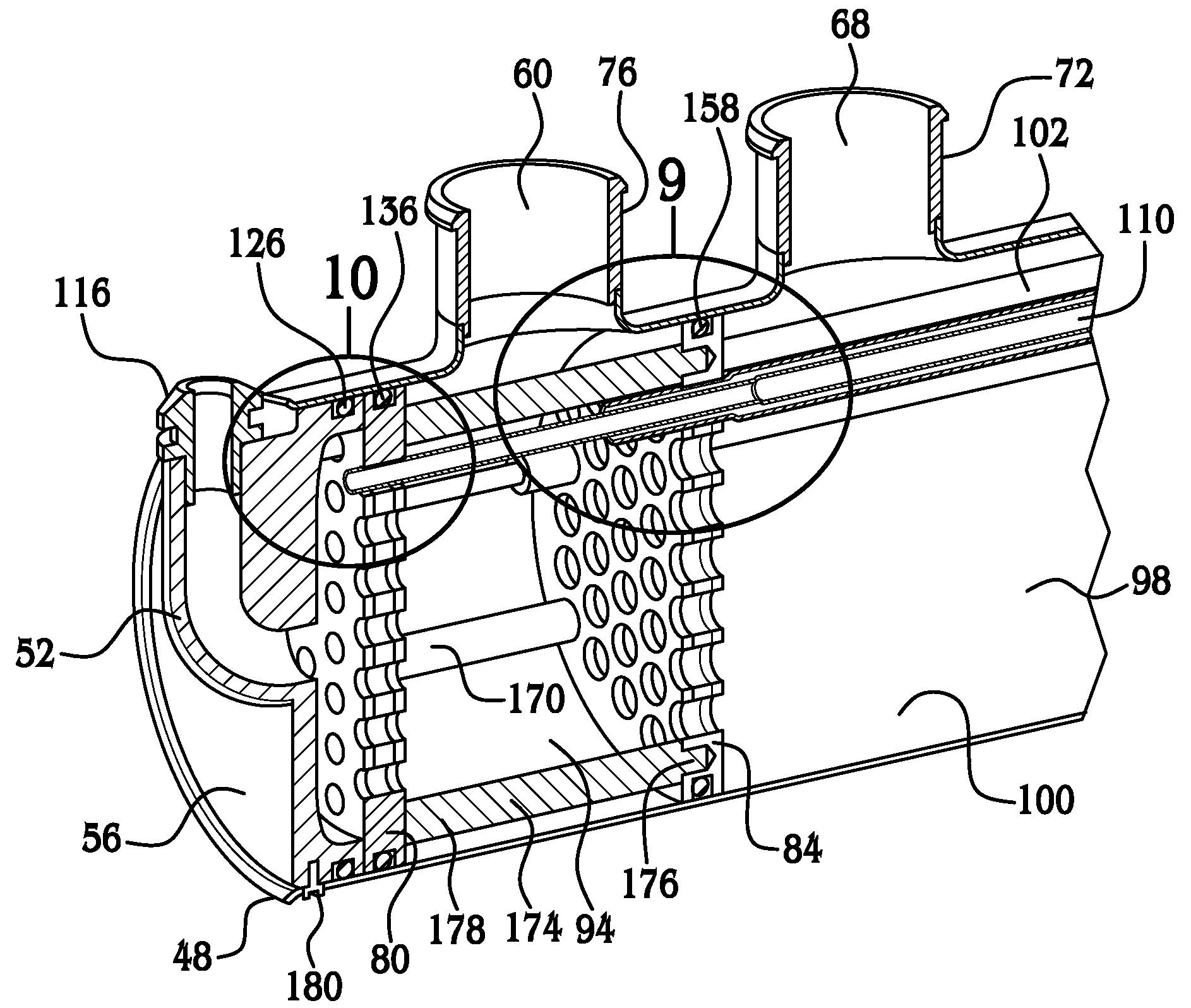
[0007]Objects, features and advantages of the present invention include a heat exchanger capable of operating with a wide and versatile range of heat transfer profiles and that has a removable core for maintenance and easy replacement of individual tubes and other components. Other advantages include the omission of expensive manufacturing processes such as brazing, the ability to use non-corrosive, light weight and relatively inexpensive components such as plastic, a relatively simple and robust design and a long and useful life.

Problems solved by technology

Traditionally, this seal is created by an expensive brazing procedure between the copper tubes and the plates.
During operation of the heat exchanger, thermal expansion and contraction is known to cause stress cracks between various brazed seals causing a loss of seal integrity.
Moreover, known assembly methods limit the ability to feasibly manufacture a multi-pass, tubular, heat exchanger having multiple inlet and outlet chambers, thus the ability to control cooling or heating rates as a function of multiple fluid temperatures is limited.
Yet further, known brazing techniques limit or prevent cost effective maintenance and replacement of individual parts of the heat exchanger core.

Method used


Image

  • Tubular heat exchanger
  • Tubular heat exchanger
  • Tubular heat exchanger

Examples


Embodiment Construction

[0023]Although the following text sets forth a detailed description of numerous different embodiments of the invention, it should be understood that the legal scope of the invention is defined by the words of the claims set forth at the end of this patent. The detailed description is to be construed as exemplary only, and does not describe every possible embodiment of the invention because such would be impractical, if not impossible. Numerous alternative embodiments could be implemented, using either current technology or technology developed after the filing date of this patent, which would still fall within the scope of the claims defining the invention.

[0024]It should also be understood that, unless a term is expressly defined in this patent using the sentence “As used herein, the term ‘______’ is hereby defined to mean . . . ” or a similar sentence, there is no intent to limit the meaning of that term, either expressly or by implication, beyond its plain or ordinary meaning, an...


PUM


Abstract

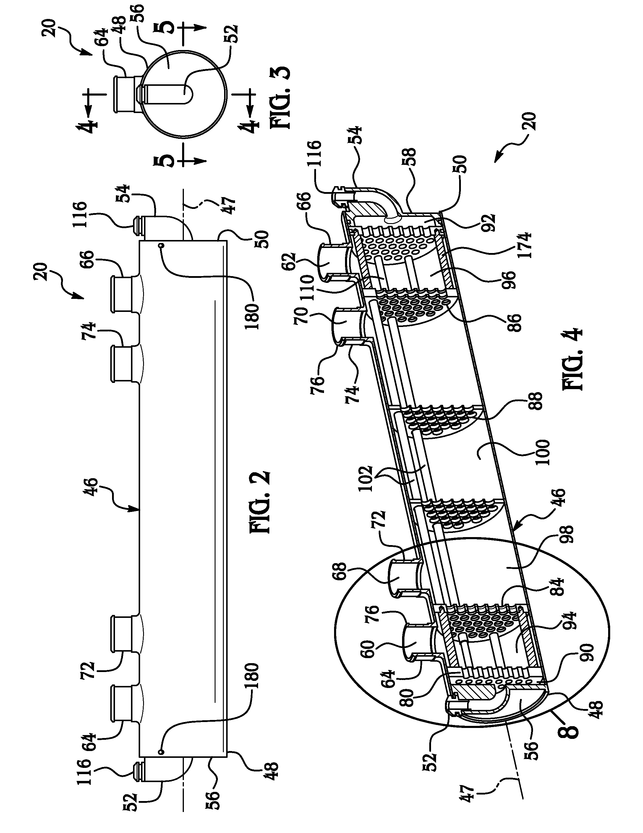
A tubular heat exchanger preferably of a multi-pass design, has a cylindrical shell with open ends that are releasable covered and sealed by preferably two end caps. Located removably in the shell and axially between the end caps is a core having a plurality of outer tubes and preferably a plurality of inner tubes with each one of the inner tubes extending through a respective one of the outer tubes. A plurality of perforated plates disposed in the shell are sealed releasably to respective ends of the inner and outer tubes thereby forming a plurality of liquid tight chambers for the flow of a plurality of segregated mediums and the transfer of heat therebetween.

Description

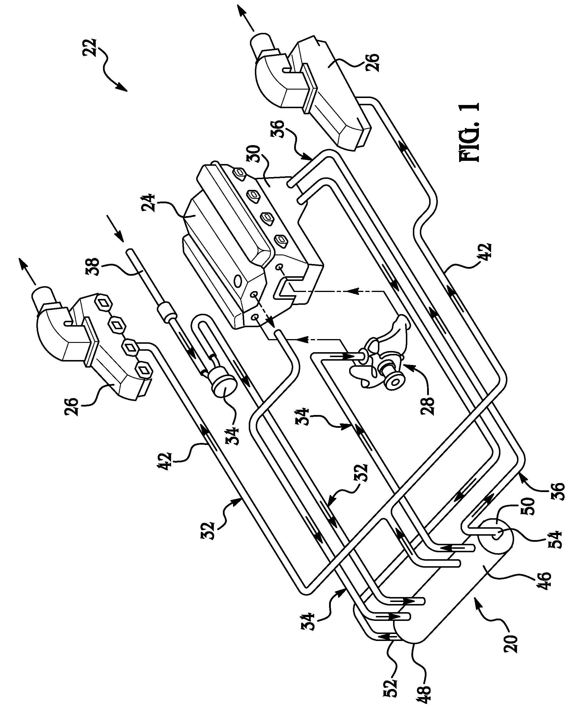
FIELD OF THE INVENTION[0001]The present invention relates to a tubular heat exchanger, and more particularly to a multi-pass, tubular, heat exchanger with a servicable core for marine applications.BACKGROUND OF THE INVENTION[0002]Tubular heat exchangers are known to flow two fluid mediums of different temperatures to transfer heat from one fluid to the other. Such heat exchangers generally have an outer shell that houses a central core having a plurality of tubes for transferring heat. The first ends of the tubes are supported by a perforated first plate sealed continuously to an inward face of the shell. The opposite second ends of the tubes are supported by a perforated second plate also sealed continuously to the inward face of the shell, thus defining a mid chamber between the plates for the flow of a first fluid medium. An inlet chamber for the flow of a second fluid is defined by the first plate and a first end of the shell, and an outlet chamber is defined by the second plate...

Claims


Application Information

Patent Timeline
Patent Type & Authority Applications(United States)
IPC IPC(8): F28F1/00F28D7/10
CPCF28D1/022F28D7/0083F28D7/106F28D7/1607F28D2021/0049F28F2280/02F28F9/0241F28F9/14F28F9/22F28F2009/226F28F9/0219
Inventor VAMVAKITIS, DIMITRI L.SLATER, MARK A.HOLDEN, JERRY L.BARRON, BRUCE M.
Owner VAMVAKITIS DIMITRI L
Why Eureka
Try Eureka